Do you have a question about the Yaesu FTR-5410 and is the answer not in the manual?
Details the technical specifications for the transmitter section.
Details the technical specifications for the receiver section.
Details the technical specifications for the internal duplexer.
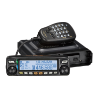
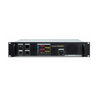
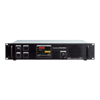
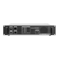
Explains the function of each front panel control and switch.
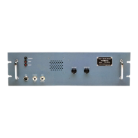
Describes the purpose and function of each rear apron connection.
Guidance on optimal antenna placement and selection for repeaters.
Recommendations for placing repeater equipment for best performance.
Explains the repeater's operation during AC power interruptions.
Details advanced operational features and control settings.
Explains the function, settings, and operation of the time out timer.
Describes the operation and purpose of the hang up delay timer.
Step-by-step guide for installing the FTS-32R Tone Squelch Unit.
Instructions for installing the FTS-5 Tone Burst Decoder unit.
Procedure for installing the optional DTMF Decoder Unit.
Procedure for installing the optional CW ID Unit.
Illustrates the frequency relationships within the FTR-710A unit.
Illustrates the frequency relationships within the FTR-2410A unit.
Illustrates the frequency relationships within the FTR-5410 unit.
Provides a high-level block diagram of the FTR-710A unit.
Provides a high-level block diagram of the FTR-2410A unit.
Provides a high-level block diagram of the FTR-5410 unit.
Detailed description of the receiver (RX) unit's circuitry.
Detailed description of the COR unit's circuitry and function.
Detailed description of the transmitter (TX) unit's circuitry.
Description of the DTMF Decoder Unit's circuitry and operation.
Procedures for aligning the receiver sections of various models.
Alignment procedures specific to the FTR-5410 Receiver Unit.
Procedures for aligning the transmitter sections of various models.
Alignment procedures for the power supply unit.
Specific alignment steps for the COR Unit.
Specific alignment steps for the DTMF Unit.
Alignment procedures for the duplexer unit.
Alignment procedures for the FL-2450 unit.
Instructions for setting the delay timers for various functions.
Details on programming DTMF command codes for unit control.
Diagram showing the interconnection of various repeater system components.
Detailed component list and layout for the FTR-710A Receiver Unit.
Detailed component list and layout for the FTR-2410A Transmitter Unit.
Schematic diagram for the FL-5450 Repeater Power Amplifier.
Component layout diagram for the FL-5450 Main Chassis.
Schematic diagram for the FP-15 AC Power Supply.
Component layout diagram for the FP-15 Main Chassis.
| Power Output | 50W |
|---|---|
| Modes | FM |
| Power Supply | 13.8 VDC |
| Channels | 16 |
| Modulation | FM |