630 YRM 1003 Special Precautions
General
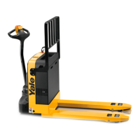
This section has the description and repair procedures
for the master drive unit (MDU). The traction motor,
steering, and brake repair procedures are in separate
sections. The main parts of the drive unit are the hous-
ing, pinion (motor), first intermediate gear set, second
intermediate gear set, drive gear, bearings, axle, wheel,
and spindle. The spindle is bolted to the top of the drive
unit has tapered bearings installed for the mounting of
the MDU to the frame. The steering control handle fas-
tens to the MDU. The traction motor fastens to the drive
unit. The drive unit and the traction motor turn as a unit
for steering.
In some instances, it may only be necessary to remove
the drive motor and brake assembly to work on the
MDU, while in other cases, the MDU must be com-
pletely removed. Determine the extent of disassembly
required before proceeding with any repairs.
See the section Steering Mechanism 1600 YRM 1004
for troubleshooting and repairs on the steering compo-
nents.
See the section Electrical System 2200 YRM 1007
and DC Motor Maintenance 620 YRM 294 for trou-
bleshooting and repairs on the electrical components
of the MDU.
See the section Brakes 1800 YRM 1005 for trou-
bleshooting and repairs of the brake components.
See the section Periodic Maintenance 8000 YRM
1048, Periodic Maintenance 8000 YRM 1379, or Pe-
riodic Maintenance 8000 YRM 1009 for instructions
on checking and changing the drive unit gear oil.
Description
TheMDUisatriplereductiondriveunit.Thethreesets
of gears do not need adjustment for wear. All the parts
that rotate have ball bearings or tapered roller bearings.
The ball bearings are lubed by gear oil and the tapered
roller bearings are packed with multipurpose #2 grease
with 2% to 4% molybdenum disulfide. A pinion gear on
the motor armature drives the first of the three reduction
gears. The second intermediate gear engages the drive
gear. The drive gear is mounted on the drive axle. The
drive axle is the mount for the final drive gear and the
wheel.
A spring applied/electrically released friction brake is
mounted to the drive motor between the motor and the
MDU. See the section Brakes 1800 YRM 1005 for ad-
ditional information on the electrical brake.
Special Precautions
WARNING
Block each side of the truck under the drive unit
frame. Position blocks on both sides of the load
wheels to prevent the truck from falling.
WARNING
The capacitor in the transistor controller can hold
an electrical charge after the battery is discon-
nected. Discharge the capacitor before inspecting
or repairing any component in the MDU compart-
ment to prevent personal injury and damage to
the electrical system. Make certain the battery has
been disconnected. DO NOT use a screwdriver
to mak
e a short circuit across the B+ and B
termi
nals of the transistor controller. Always wear
safet
y glasses.
WARNING
Perfo
rm the following steps before performing any
troub
leshooting or adjustments, and before con-
nect
ing or disconnecting a handset or personal
comp
uter to avoid personal injury and prevent
elec
trical shock.
1. Veri
fy that the key switch is in the OFF position and
the b
attery connector is completely disconnected.
1