1800 YRM 1005 Brake Assembly Repair
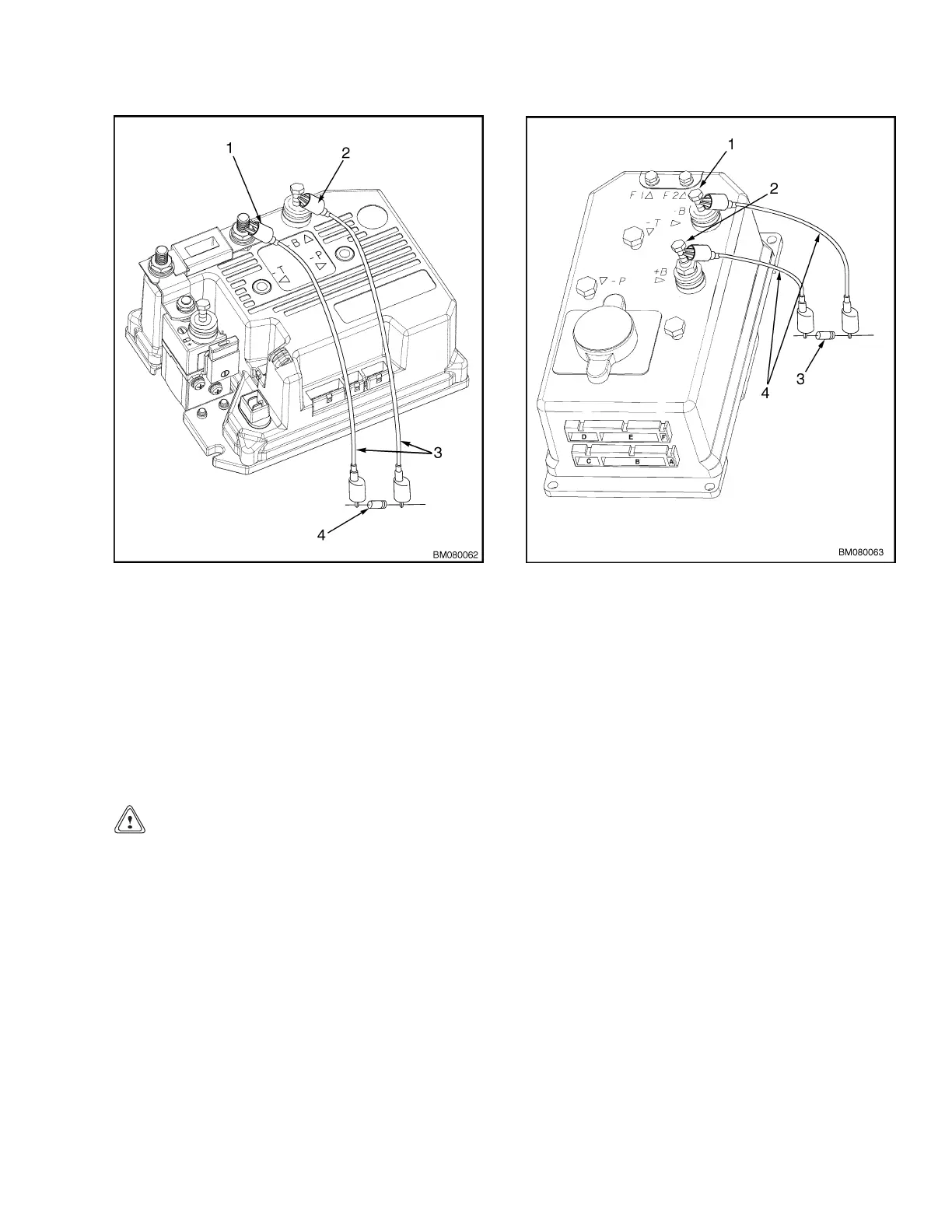
1. POSITIVE CONNECTION
2. NEGATIVE
CONNECTION
3. INSULATED JUMPER WIRES
4. 200-OHM, 2-WATT RESISTOR
Figure 2. Discharging Controller MPB040-E
1. NEGATIVE CONNECTION
2. POSITIVE
CONNECTION
3. 200-OHM, 2-WATT RESISTOR
4. INSULATED JUMPER WIRES
Figure 3. Discharging Controller MSW020/025-E,
MSW025/030-F, and MPW045/050-E
Brake Assembly Repair
BRAKE OVERRIDE
CAUTION
Never operate the lift truck while the brake override
feature is being used.
The brake can be disengaged when a truck cannot be
operated but needs to be moved. On the main wiring
harness approximately 300 mm (12 in.) above the
MDU, the brake wiring harness is connected. An extra
four pin connector for the brake override feature is
secured near this connection with wire ties. Disconnect
the connectors and connect the brake wiring harness
to the brake override connector. This will energize
the brake coil which will release the brake. The drive
motor will not activate while the jumper is installed.
Roll the lift truck to a safe location and disconnect
the brake override connector. The brake will apply
when the brake override connector is disconnected or
when power to the brake override circuit is interrupted.
Reconnect the brake wiring harness to the main wiring
harness and proceed with repairs. If the battery does
not have sufficient charge, or if certain components of
the lift truck are damaged, the brake may not release
with the brake override circuit engaged. In this case,
the malfunction must be corrected before the brake can
be released. See Figure 4.
3