100 YRM 1015 General
General
DESCRIPTION
The main frame has mounts for the lifting mechanism,
the electrical system parts, the hydraulic pump assem-
bly, and the master drive unit (MDU). Repair procedures
for major systems/parts that fasten to the main frame
are found in separate YRM manuals.
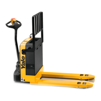
Models with a fork frame weldment have mounts for the
lifting mechanism. See Figure 1. The fork frame weld-
ment is fastened to the main frame by the links of the
lifting mechanism. The base of the forks and the bat-
tery end of the weldment are lifted by the cylinder to
raise the load. At the same time, the fork tips are lifted
by linkage operating the load wheel assembly. There
is also a mount for the optional casters. The mounting
holes for the casters are in the main frame weldment.
1. FORKS
2. FRAME
3. UPPER COVER
4. MOTOR COVER (LH)
5. MOTOR COVER (RH)
6. COUNTERSUNK CAPSCREW
7. LOWER COVER
8. WASHER
9. BUTTON HEAD CAPSCREW
Figure 1. Frame Weldment and Covers MPB040-E, MPW045-E, and MPW050-E
1