1800 YRM 1005 Description
General
WARNING
DO NOT operate a lift truck that needs repairs. If a
repair is necessary, put a DO NOT OPERATE tag on
the control handle. Remove the key from the key
switch.
WARNING
Before performing repairs or adjustments on the
brake system, blocks must be placed under each
sideoftheframetoraisethedrivetireoffthe
ground. The blocks must prevent the lift truck from
falling and causing personal injury or property
damage. See Periodic Maintenance 8000 YRM
1009, Periodic Maintenance 8000 YRM 1379, or
Periodic Maintenance 8000 YRM 1048, How to Put
a Lift Truck on Blocks.
WARNING
Always disconnect and separate the battery con-
nector so that the connector is completely free be-
fore performing any service or repairs. If the con-
nector is not completely free, it can reconnect. Tag
the connector: DO NOT CONNECT.
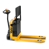
This section has the description and repair procedures
for the electric brake on the MSW020-E, MSW025-E,
MSW025-F, MSW030-F, MPB040-E, MPW045-E, and
MPW050-E lift trucks. Brake assemblies may vary in
appearance. Although some assemblies may APPEAR
to be adjustable, brake assemblies used on these trucks
ARE NOT ADJUSTABLE. Friction between parts inside
the brake will produce brake dust, squeaking, and ex-
treme heat under normal operating conditions. Brake
assemblies can generate surface temperatures up to
130
C(266 F) and odors during heavy operation. Func-
tions of the brake assembly depend on a dry and clean
environment. Small amounts of oil or grease on the fric-
tion surfaces of the brake can seriously compromise the
brakes ability to function.
Description
Motorizedhandtruckshavethreemethodsofbraking:
1. Regenerative (Neutral) braking
2. Controlled plugging
3. Application of the spring-applied/electrically re-
leased friction brake
NOTE: The preferred method of stopping the truck is:
Regenerative (Neutral) braking
or
Controlled plugging
Regenerative (Neutral) braking applies a retarding force
to the drive wheel through the traction motor, allowing
the unit to slow to a gradual stop. It is applied by re-
turning the speed/direction control to the NEUTRAL po-
sition or by placing the hand brake lever(s) in the first
stage position.
Controlled plugging is reversing the speed/direction
control while traveling, causing the unit to slow to a stop.
Return the speed/direction control to the NEUTRAL
position to remain stopped. If the speed/direction
control is not returned to the NEUTRAL position after
the truck is stopped, the lift truck will accelerate in the
direction the handle is being turned. Controlled plug-
ging should stop the truck within a few feet, depending
on speed and load.
The parking brake is a spring-applied, electrically re-
leased friction brake mounted to the drive motor. When
the parking brake is applied, springs inside the brake
assembly compress a rotating friction disk against two
stationary plates.
To release the brake:
1. Connect the battery.
2. Turn the key switch to the ON position.
3. Lower the control handle arm to the operating or
BRAKE OFF position. Refer to Figure 1.
4. Rotate direction/speed control (butterfly knobs) in
the direction of travel.
1