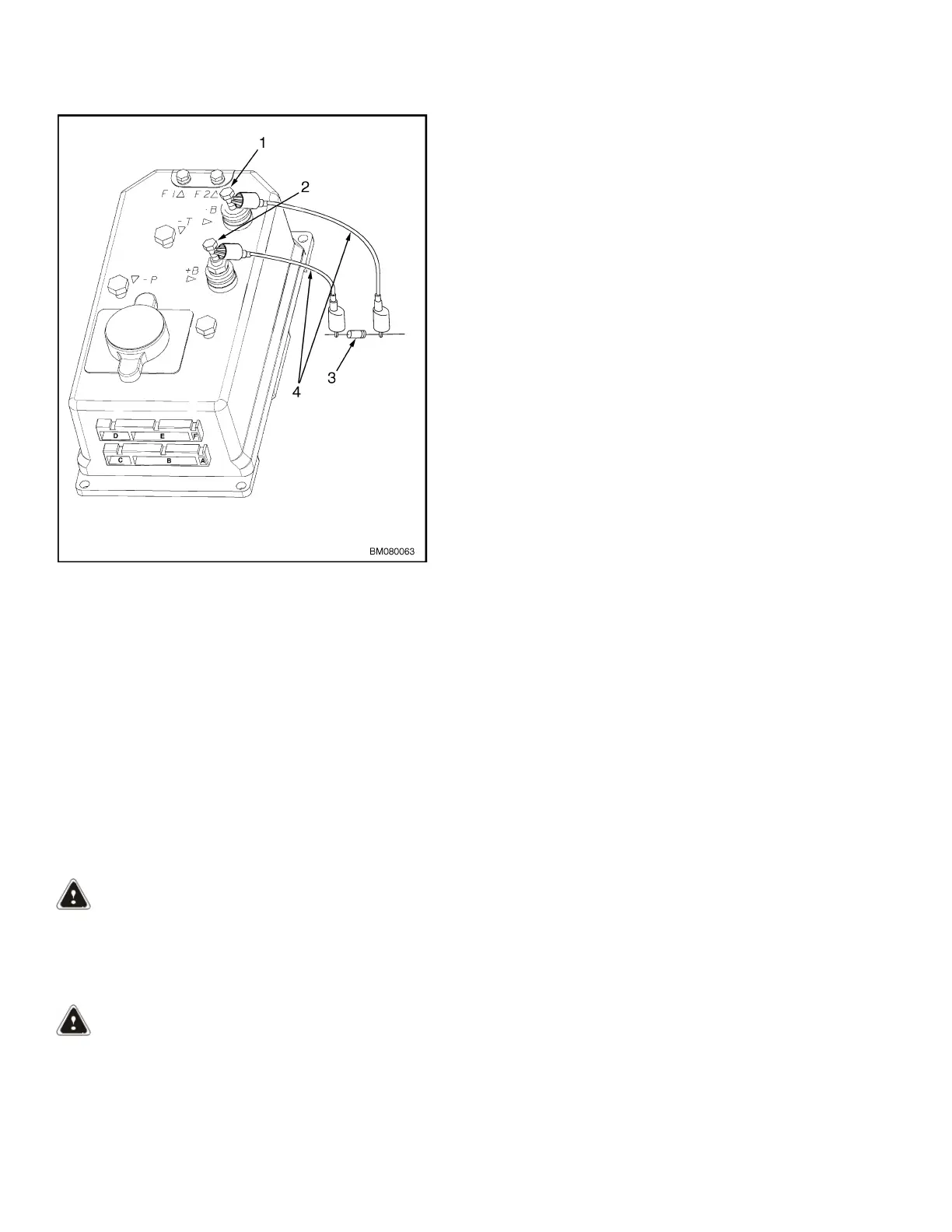
Figure 2. Discharging Controller - MSW020-E,
MSW025-E, MSW025-F, MSW030-F, MPW045-E,
and MPW050-E
Legend for Figure 2
1. NEGATIVE CONNECTION
2. POSITIVE CONNECTION
3. 200-OHM, 2-WATT RESISTOR
4. INSULATED JUMPER WIRES
Control Handle Head
Refer to the section Electrical System
2200YRM1007 for instructions on removing and in-
stalling the control handle head from the control han-
dle. The instructions for disassembly and assembly of
the control handle head can be located in the same
section.
Control Handle
REMOVE
WARNING
The gas springs used on the control handle are
installed under tension and can release with
enough force to cause personal injury or property
damage.
WARNING
The capacitor in the transistor controller can hold
an electrical charge after the battery is disconnec-
ted. To prevent electrical shock and personal in-
jury, discharge the capacitor before inspecting or
repairing any component in the drive unit com-
partment. Wear safety glasses. Make certain the
battery has been disconnected. Refer to Figure 1
and Figure 2 in the Special Precautions section of
this manual.
1. Move the lift truck to a safe, level area and block
the wheels to prevent movement.
2. Turn the key switch to the OFF position and dis-
connect the battery.
3. Remove the drive unit compartment covers and
MDU covers.
Special Precautions 1600 YRM 1004
2