Install
1. Insert the proximity switch fully into the switch
bracket. Route the proximity switch wire so that it
will not be pinched or damaged when the control
handle is installed.
CAUTION
DO NOT damage the plastic switch bracket or
proximity switch by overtightening screws.
2. Install the proximity switch assembly to the drive
unit housing with two capscrews through the
switch bracket into the drive unit housing. DO
NOT tighten the capscrews until after the switch
has been adjusted.
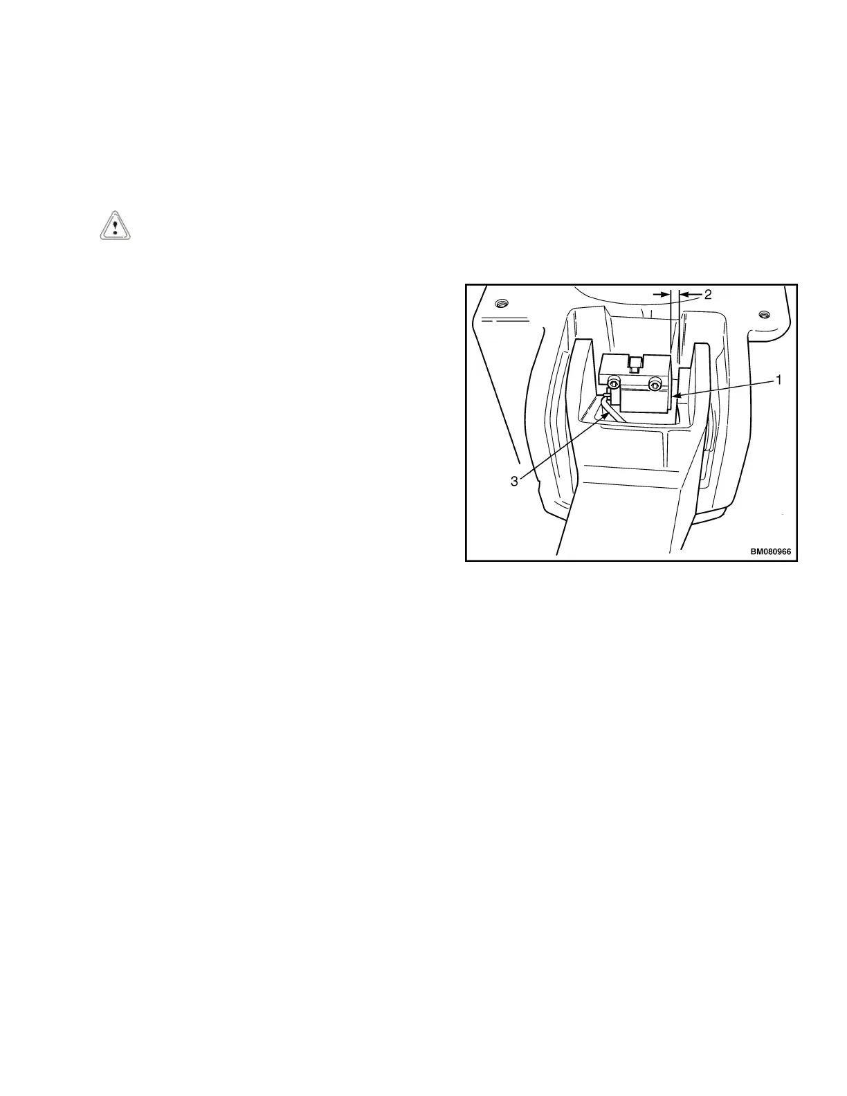
3. Check the gap between the proximity switch as-
sembly and the control handle. The gap should
measure 3.0 to 5.0 mm (0.12 to 0.20 in.) See Fig-
ure 11. If the gap distance is different, horizontally
adjust the location of the proximity switch.
4. Connect the switch to the wiring harness.
5. Connect the battery and turn the key switch to the
ON position.
6. With the handle at 10° from vertical, move the
proximity switch until the LED turns on.
7. Slowly move the proximity switch in the opposite
direction until the LED just turns off.
8. Torque the two capscrews to 4.17 N•m (37 lbf in).
9. Verify that the truck operates correctly with the
handle in the following positions:
a. LED comes on with the handle in RUN posi-
tion.
b. LED should go off with the handle approxi-
mately 10° from vertical position.
10. Install the two shield covers using four capscrews
11. Install the lower drive unit compartment cover.
12. Install the upper drive unit compartment cover.
1. PROXIMITY SWITCH ASSEMBLY
2. GAP 3.0 TO 5.0 mm (0.12 TO 0.20 in.)
3. PROXIMITY SWITCH WIRE
Figure 11. Proximity Switch Assembly Location
2200 YRM 1007 Control Handle Arm Proximity Switch
17
 Loading...