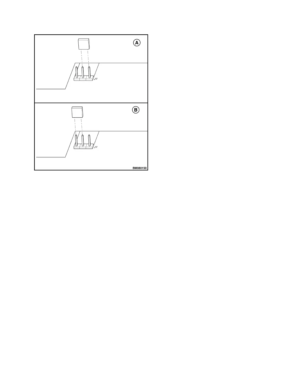
A. RUN MODE B. CALIBRATE MODE
Figure 12. Control Handle Card Calibration
8. With the handle in the full upright position, turn
the key switch to the ON position.
9. Slowly rotate the butterfly knobs in the forward di-
rection and hold at maximum rotation for 5 sec-
onds.
10. Slowly rotate the butterfly knobs back to the neu-
tral position and leave for 5 seconds.
11. Slowly rotate the butterfly knobs in the reverse di-
rection and hold at maximum rotation for 5 sec-
onds.
12. Slowly rotate the butterfly knobs back to the neu-
tral position and leave for 5 seconds.
NOTE: If control handle includes the optional propor-
tional switches, it will be necessary to perform
Step 13 through Step 16. If control handle includes
only the full speed and half speed ON/OFF lift and
lower switches, then go to Step 17.
13. Slowly press the proportional LIFT button and
hold down five seconds.
14. Slowly release the proportional LIFT button and
wait for five seconds.
15. Slowly press the proportional LOWER button and
hold down for five seconds.
16. Slowly release the proportional LOWER button
and wait for five seconds.
17. Move the jumper on the J1 terminal to the RUN
mode. See Figure 12, view A.
18. Turn the key switch to the OFF position.
19. Install the upper half on the lower half. Refer to
Assemble for instructions on how to install the up-
per half on the lower half.
20. Test the lift truck to verify correct travel, lift, and
lower speeds.
CONTROL HANDLE CARD (NEW STYLE)
NOTE: New style control handle cards will be blue in
color and should be used as replacement cards re-
gardless of color of the card removed. If simply cali-
brating an existing old style card (green in color), refer
to Control Handle Card (Old Style).
NOTE: Verify that the magnetic holder of the thumb-
wheel switch has been installed in the proper position.
See Figure 13.
After servicing the control handle head, it may be nec-
essary to configure and/or calibrate the control handle
card.
2200 YRM 1007 Control Handle
19
 Loading...