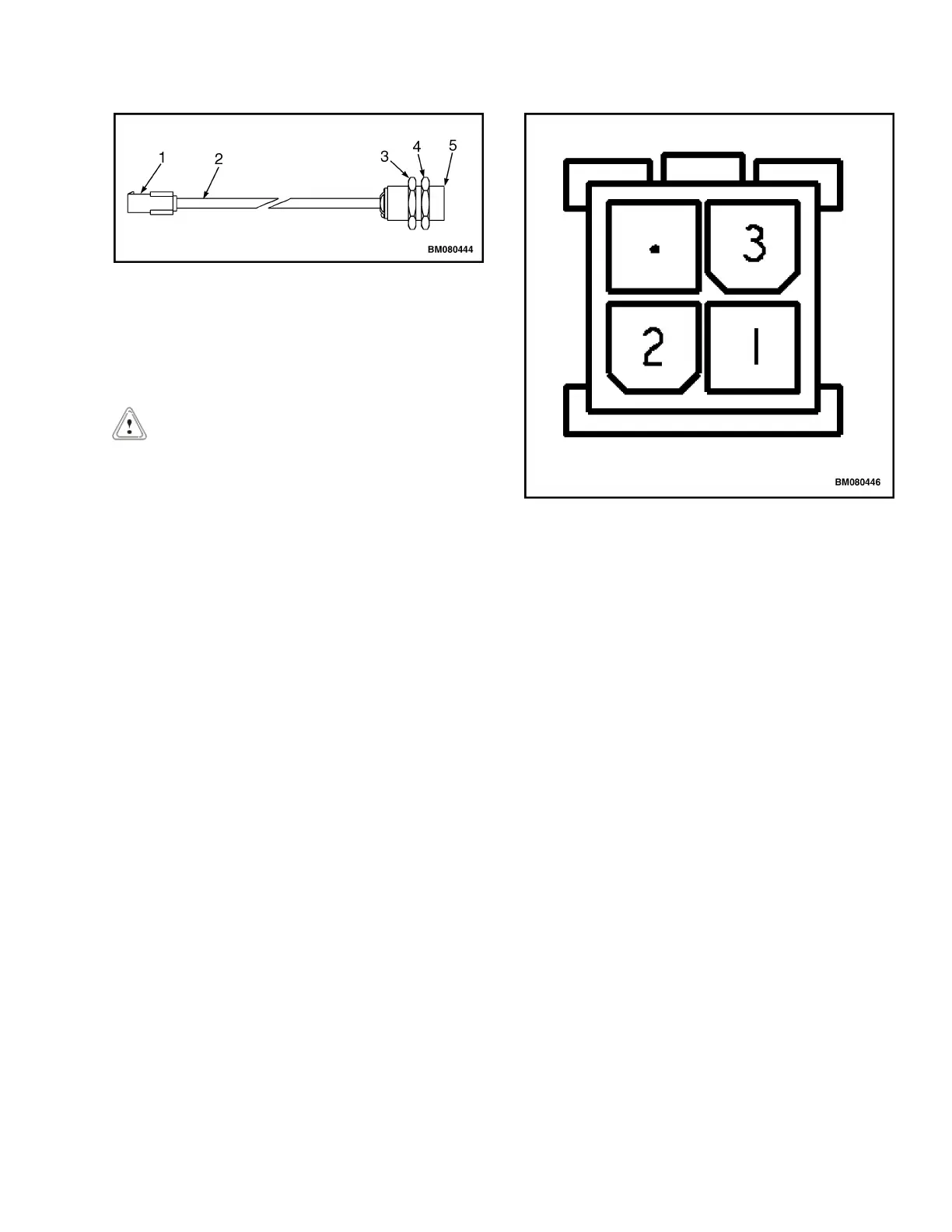
1. SENSOR CONNECTOR
2. SENSOR WIRING
3. REAR JAM NUT
4. FRONT JAM NUT
5. SENSOR FACE
Figure 20. Sensor and Jam Nuts
CAUTION
DO NOT connect jumper wires to the truck wiring
harness.
2. Connect jumper wires to the sensor wiring har-
ness:
a. Connect positive (24 volts) to the pin #1 of the
connector. See Figure 21.
b. Connect a ground to the pin #2 of the connec-
tor.
c. Connect a voltmeter between pin #3 of the
connector and a ground.
3. Position a piece of metal within 5.0 mm (0.2 in.) of
the face of the sensor to activate the sensor. Re-
move your hand to deactivate. Voltmeter should
read 24 volts when the sensor is activated and no
voltage when it is deactivated. If the sensor does
not operate correctly, it must be replaced.
Install
1. Position the rear jam nut onto the position sensor
threads.
2. Install the position sensor into the bracket on the
frame of the lift truck as removed.
3. Install the front jam nut onto the position sensor
threads. Snug jam nut to secure sensor in place.
1. PIN #1 (BROWN WIRE)
2. PIN #2 (BLUE WIRE)
3. PIN #3 (BLACK WIRE)
Figure 21. Sensor Connector (Front View)
4. Connect the sensor wiring connector to the truck
wiring harness connector as removed.
Adjust
1. Slightly loosen the front jam nut of the lift linkage
proximity sensor.
2. Adjust both jam nuts equally to position the prox-
imity sensor 2.5 mm (0.1 in.) from the upper lift
linkage when the forks are in the fully raised posi-
tion.
3. Tighten the front jam nut to secure the proximity
sensor in position. Verify the measurement.
4. Check for proper operation.
2200 YRM 1007 Lift Link Proximity Sensor (MPW050-E)
31
 Loading...