5-18
POWR
E
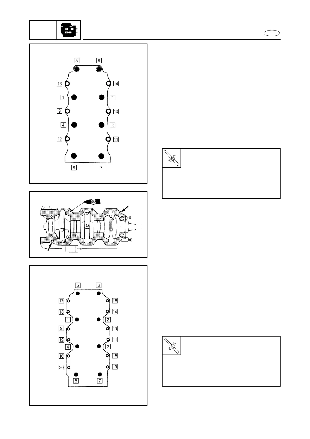
ASSEMBLY AND ADJUSTMENT
2. Lift the crank assembly a little in order
to install a washer on the lower crank-
case and align each location-pin of the
bearings and labyrinth-seals with each
cut on the cylinder-block. Then, fit the
crank assembly in place.
3. Film-coat the cylinder-block mating sur-
face with Gasket Maker or equivalent.
4. Install the dowel-pins.
5. Match the cylinder-block and tighten
the bolts to the specified torque in
sequence and in two steps.
6. Check that the crankshaft turns
smoothly.
G74002-0*
CRANK CYLINDER ASSEMBLY
(75, 80, 90 hp)
1. Align each locating-pin of the bearings
and labyrinth-seals with each cut on the
cylinder-block. Then, fit the crank
assembly in place.
2. Film-coat the cylinder-block mating sur-
face with Gasket Maker or equivalent.
3. Install the dowel-pins.
4. Match the cylinder-block and tighten
the bolts to the specified torque in
sequence and in two steps.
5. Check that the crankshaft turns
smoothly.
T
R
.
.
Crankcase bolt (50, 60, 70 hp)
1st step:
M8: 10 Nm (1.0 m • kg, 7.2 ft • lb)
M10: 20 Nm (2.0 m • kg, 14 ft • lb)
2nd step:
M8: 20 Nm (2.0 m • kg, 14 ft • lb)
M10: 40 Nm (4.0 m • kg, 29 ft • lb)
T
R
.
.
Crankcase bolt (75, 80, 90 hp)
1st step:
M6: 4 Nm (0.4 m • kg, 2.9 ft • lb)
M10: 20 Nm (2.0 m • kg, 14 ft • lb)
2nd step:
M6: 12 Nm (1.2 m • kg, 8.7 ft • lb)
M10: 40 Nm (4.0 m • kg, 29 ft • lb)