CS2X
10
When you re-install the LC circuit board, you should
tighten the screws marked [60B] in the oeder of a, b
shown in the figure. (Fig. 5)
5-5 After the LC circuit board has been removed, the
reflection sheet can then be removed. After that,
remove both the back-lit lens with the rubber
connectors and the LCD.
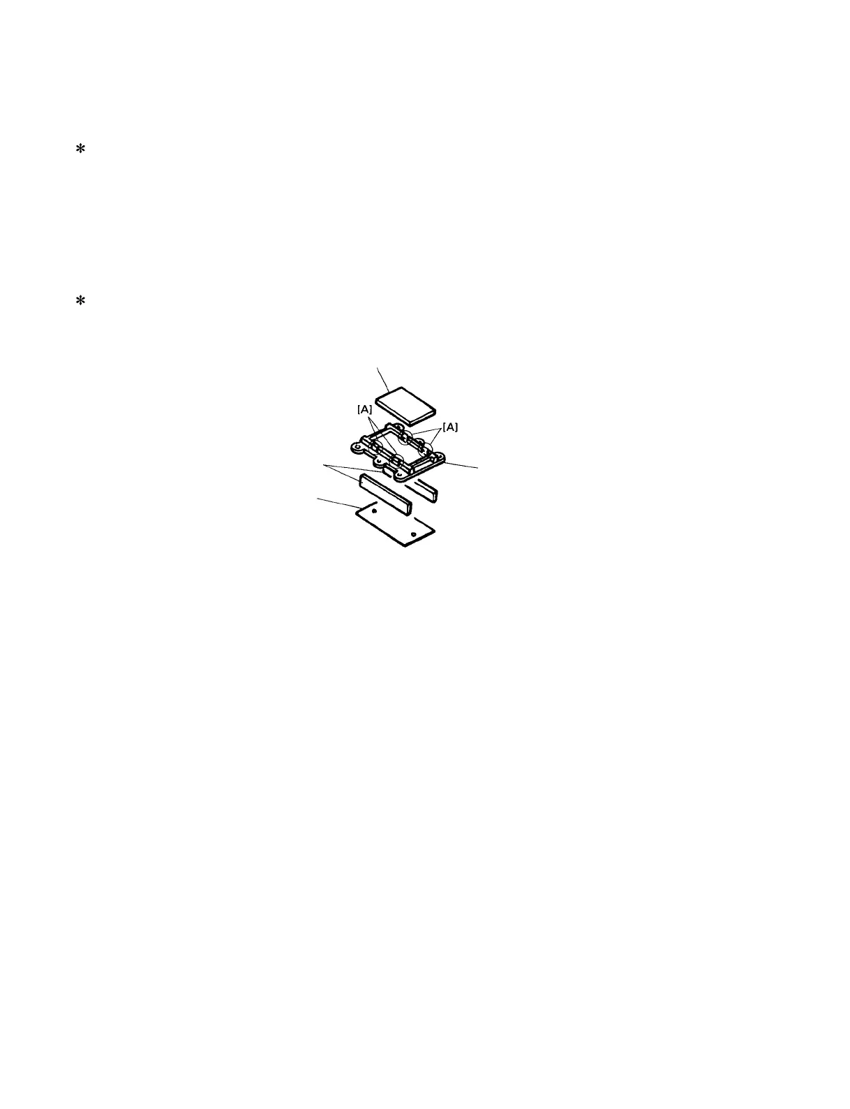
5-6 While pushing the hooks marked [A], take the LCD
out of the back-lit lens. (Fig. 6)
When you re-install the LCD, put the projection side
at the slit of the rib of the upper case.
Fig.6
Reflection sheet
Rubber connectors
Lens, back-lit
LCD
6. Wheel Assembly
6-1 Remove the bottom assembly. (See Procedure 1.)
6-2 Remove the four (4) screws marked [200]. The wheel
assembly can then be removed. (Fig. 5)
7. Disassembling the Keyboard Assembly
7-1 Remove the bottom assembly. (See Procedure 1.)
7-2 Remove the DM circuit board with the shield box.
(See Procedure 2-2.)
7-3 Remove the keyboard assembly. (See Procedure 3.)
7-4 Remove the two (2) screws marked [30]. The MKS2
circuit board can then be removed. (Fig. 2)
7-5 Remove the MK circuit board while pressing the
fifteen (15) hooks inward, and then remove the
rubber contact. (Fig. 7)
7-6 Remove the twenty-one (21) screws marked [140],
then remove the black keys from the lower notes.
Afterwards, remove the white keys DFA and C’ and
then remove the white keys CEGB from the higher
notes. At this time, lift the keys from the front and slide
them towards you. The keys can then be removed
from the assembly (Fig.8)
 Loading...