CS2X
9
4. PN1/2 & PN2/2 Circuit Boards
4-1 Remove the bottom assembly. (See Procedure 1.)
4-2 Remove the DM circuit board with the shield box.
(See Procedure 2-2.)
4-3 Pull off the ten (10) knobs.
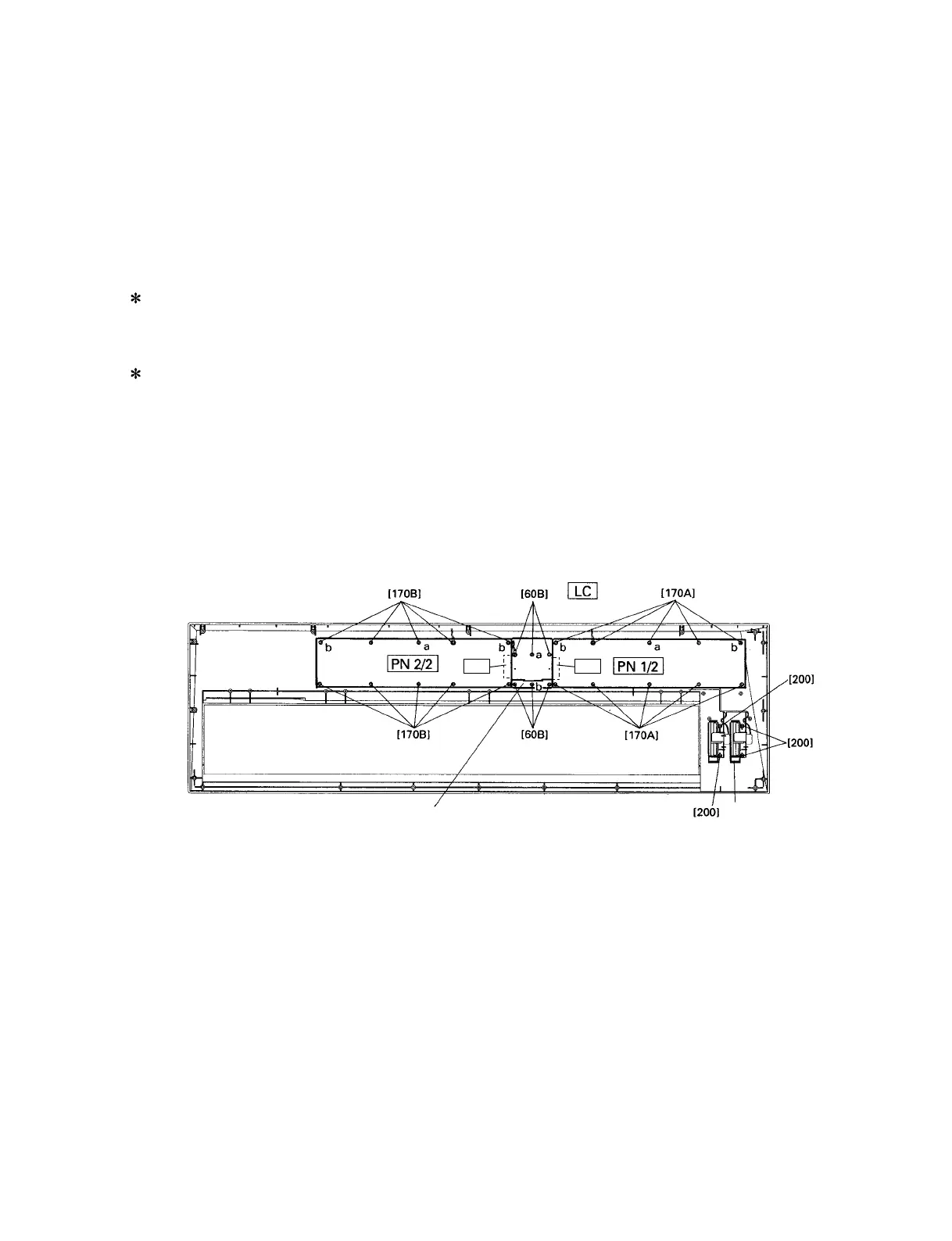
4-4 Remove the ten (10) screws marked [170A]. The
PN 1/2 circuit board can then be removed. (Fig. 5)
The LE 1/2 circuit board is mounted on the PN 1/2
circuit board.
4-5 Remove the ten (10) screws marked [170B]. The
PN 2/2 circuit board can then be removed. (Fig. 5)
The LE 2/2 circuit board is mounted on the PN 2/2
circuit board.
4-6 When you re-install the PN 1/2 and PN 2/2 circuit
boards, you should tighten the screws marked [170A]
and [170B] in the order of a, b.
[60B]: Bind Head Tapping Screw-P 3.0X8 MFZN2Y (EP630280)
[170A]: Bind Head Tapping Screw-P 3.0X8 MFZN2Y (EP630280)
[170B]: Bind Head Tapping Screw-P 3.0X8 MFZN2Y (EP630280)
[200]: Bind Head Tapping Screw-P 3.0X8 MFZN2Y (EP630280)
LE LE
Fig.5
Wheel assembly
Spacer
5. LC Circuit Board & LCD
5-1 Remove the bottom assembly. (See Procedure 1.)
5-2 Remove the DM circuit board with the shield box.
(See Procedure 2-2.)
5-3 Remove the PN 1/2 or PN 2/2 circuit board.
(See Procedure 4.)
5-4 Remove the six (6) screws marked [60B]. The spacer
and the LC circuit board can then be removed. (Fig. 5)