CS2X
26
T27. FACTORY SETTING
27 FACTORY
This test is used to initialize the data to the factory
settings.
If you press the [ENTER], the factory preset data will be
restored and the test will end.
After the factory preset data has been restored, the
system data will be as follows:
(Factory setting data)
SYSTEM SETUP
USER PERFORMANCE
The 128 user performance data of the factory preset data
will be restored.
FACTORY PRESET MODE & VOICE NUMBER
MODE: PERFORMANCE MODE
PERFORMANCE NUMBER: PRESET 1
Set the voice number to 1, after setting sound control
knobs to the positions listed below.
System Setup Data
T28. EXIT TEST PROGRAM
28 EXIT
To exit the test program mode, press the [ENTER] switch.
After exiting the test program mode, measure the noise
level of each output never playing on any key on the
keyboard. While measuring the noise level, use an AC
voltmeter (with JIS-C filter).
OUTPUT L: less than -80 dBm (10k ohm load)
OUTPUT R: less than -80 dBm (10k ohm load)
PHONES L: less than -90 dBm (33 ohm load)
PHONES R: less than -90 dBm (33 ohm load)
T29. INPUT TEST
This test is performed in the normal mode.
Confirm that the signal input to the INPUT is output to
the LINE OUT.
Connect a standard plug to the LINE OUT (L,R) and
measure that the frequency and the output level of each
output are as follows.
INPUT L: 1k Hz, 2.5 dBm, sine wave
INPUT R: GND
LINE OUT L: 2.5 dBm +/- 2 dBm (10k ohm load)
LINE OUT R: less than -70 dBm
INPUT L: GND
INPUT R: 1k Hz, 2.5 dBm, sine wave
LINE OUT L: less than -70 dBm
LINE OUT R: 2.5 dBm +/- 2 dBm (10k ohm load)
T30. BATTERY TEST
After waiting 30 seconds or more after the power switch
has been turned is off, perform the test without turning
the power switch on.
Confirm that the voltage it between TP and GE on the
DM circuit board and is +2.7 V or more.
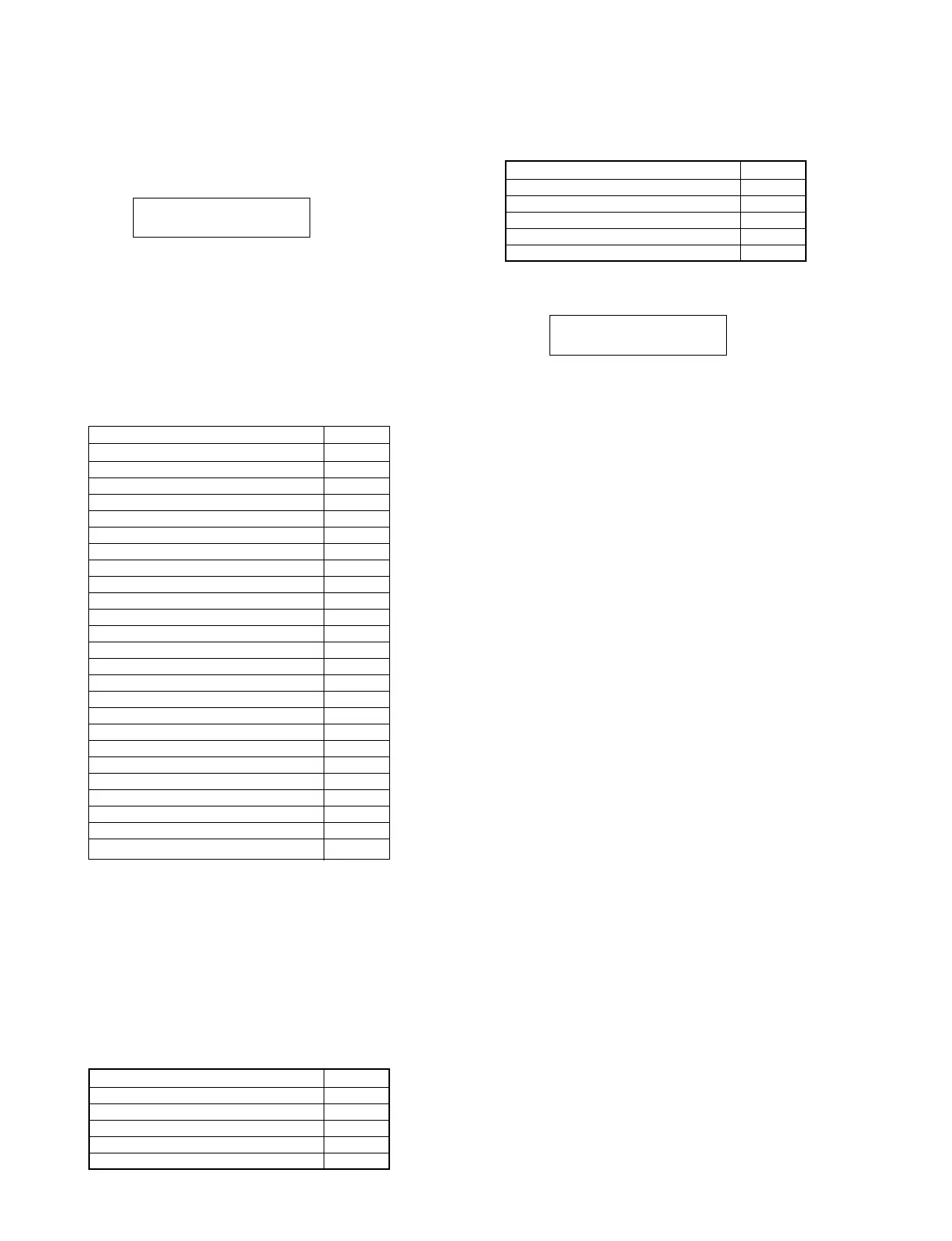
Master Tune +0(cent)
Master Volume 127
Transpose +0
MIDI Performance Receive Channel 1
MIDI Device Number ALL
Sound Module Mode PFM
Keyboard Transpose +0
Keyboard Velocity Curve NORMAL
Keyboard Fix Velocity OFF
Keyboard Velocity Transmit Channel 1
Midi Local ON
MW Control Number 1
FC Control Number 16
FV Control Number 11
Data Knob 1 Control Number 73
Data Knob 2 Control Number 80
Data Knob 3 Control Number 72
Data Knob 4 Control Number 17
Data Knob 5 Control Number 81
Data Knob 6 Control Number 74
Data Knob 7 Control Number 71
Data Knob 8 Control Number 18
Foot Switch Control Number 64
Scene Controller Number MN
Scene Mode OFF
ATTACK Knob center
DECAY Knob center
RELEASE Knob center
HPF CUTOFF Knob center
LPF CUTOFF Knob center
RESONANCE Knob center
ASSIGNABLE Knob 1 center
ASSIGNABLE Knob 2 center
EDIT PARAMETER SELECT Knob most top
VOLUME Knob minimum
PITCH BEND WHEEL center
MODULATION WHEEL minimum
 Loading...