EasyManua.ls Logo

Yamaha DS55 - Page 34

Yamaha DS55
39 pages
Print Icon
To Next Page IconTo Next Page
To Previous Page IconTo Previous Page
Loading...
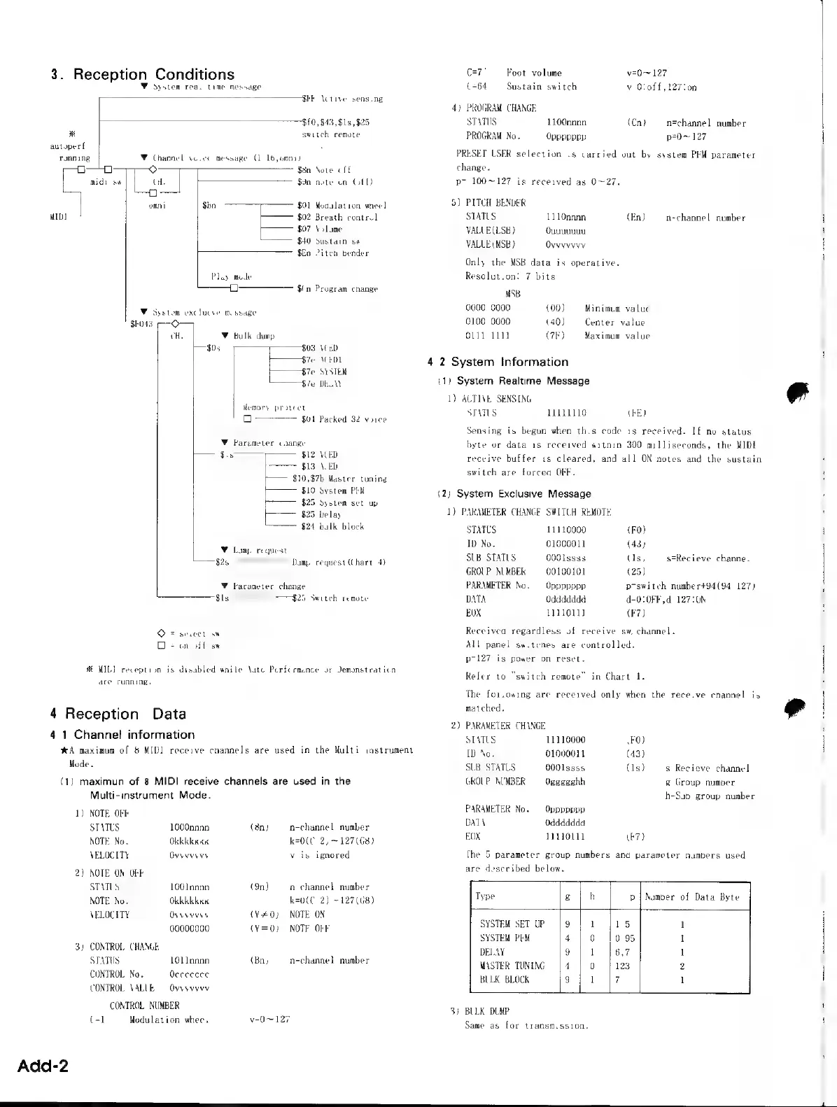
3.
Reception
Conditions
Y
System
real
time
message
$FE
Active
sensing
$f0,
$43,915,
$25
x
switch
remote
autoperf
running
Y
Channel
voice
message
(1
16,0mni)
m}
0
Q
$8n
Note
off
midi
sw
CH.
NA
$9n
note
on
(off)
0
omni
$8n
$01
Modulation
wheel
MIDI
$02
Breath
control
$07
Volume
$40
Sustain
sw
$En
Pitch
bender
Play
mode
Sin
Program
change
Y
System
exclueve
message
CH.
Y
Bulk
dump
$0s
$03
VCED
Po
876
ACEDL
t———$7e
SYSTEM
———$7e
DELAY
Memory
protect
$04
Packed
32
voice
Y
Parameter
change
$ls
$12
VCED
$13
ACED
r—
$10,87b
Master
tuning
$10
System
PFM
$25
System
set
up
$25
Delay
$24
bulk
block
W
Dump
request
$2
————
Dump
request
(Chart
4)
W
Parameter
change
$ls $25
Switch
remote
O
=
select
sw
o
=
onsoff
sw
X
MIDI
reception
is
disabled
while
Auto
Performance
or
Demonstration
are
running.
4
Reception
Data
4-1
Channel
information
XA
maximum
of
8
MID]
receive
channels
are
used
in
the
Multi-
instrument
Mode.
(1)
maximun
of
8
MIDI
receive
channels
are
used
in
the
Multi-instrument
Mode.
1)
NOTE
OFF
STATUS
1000nana
(8n)
n=channel
number
NOTE
No.
Okkkkkkk
k=0(0-2)
~127 (G8)
VELOCITY
Ovvvvvvv
v
is
ignored
2)
NOTE
ON/OFF
STATUS
1001nnnn
(9n)
n=channel
number
NOTE
No.
Okkkkkkk
k=0(C
2)
~127(G8)
VELOCITY
Ovvvvvvv
(V#0)
NOTE
ON
00000000
(Y=0)
NOTE
OFF
3)
CONTROL
CHANGE
STATUS
1011nnnn
(Bn)
n=channel
number
CONTROL
No.
Occecece
CONTROL
VALUE
Ovvvvvvv
-
CONTROL
NUMBER
(=1
Modulation
wheel
v=0~
127
Add-2
C=7'
Foot
volume
v=0~
127
C=64
Sustain
switch
v-0:off,127:0n
4)
PROGRAM
CHANGE
STATUS
1100nnnn
{Cn}
n=channel
number
PROGRAM
No.
Oppppppp
p=0~
127
PRESET/USER
selection
is
carried
out
by
system
PEN
parameter
change.
p=
100~127
is
received
as
0~27.
5)
PITCH
BENDER
STATUS
1110nnnn
(En)
n=channel
number
VALUE
(LSE)
Quuuuuuu
VALUE
(MSB)
Ovyvvvvv
Only
the
MSB
data
is
operative.
Resolution:
7
bits
MSB
--
0000 0000
(00)
Minimum
value
0100 0000
(40)
`
Center
value
0111
1111
(7F)
Maximum
value
4-2
System
Information
(1)
System
Realtime
Message
1)
ACTIVE
SENSING
STATUS
11111110
(FE)
Sensing
is
begun
when
this
code
is
received.
If
no
status
byte
or
data
is
received
within
300
milliseconds,
the
MIDI
receive
buffer
is
cleared,
and
all
ON
notes
and
the
sustain
switch
are
forced
OFF.
(2)
System
Exclusive
Message
1)
PARAMETER
CHANGE
SWITCH
REMOTE
STATLS
11110000
(FO)
ID
No.
01000011
(43)
SUB
STATUS
0001ssss
(1s)
s=Recieve
channel
GROUP
NUMBER
00100101
(25)
PARAMETER
No.
Oppppppp
p=switch
number+94(94
127)
DATA
Oddddddd
d=0:0FF,d=127:0N
EOX
1111011]
(F7)
received
regardless
of
receive
sw/channel.
All
panel
switches
are
controlled.
p=127
is
power-on
reset.
eler
to
"switch
remoteā€
in
Chart
1.
The
following
are
received
only
when
the
receive
channel
is
matched.
2)
PARAMETER
CHANGE
STATUS
11110000
(FO)
D
No.
01000011
(43)
SUB
STATUS
0001ssss
(1s)
s=Recieve
channe
GROUP
NUMBER
Ogegeghh
g-Group
number
h=Sub
group
number
PARAMETER
No.
`
Oppppppp
DATA
Oddddddd
FOX
11130111
(F7)
The
5
parameter
group
numbers
and
parameter
numbers
used
are
described
below.
Type
g
h
|
p
|
Number
of
Data
Byte
SYSTEM
SET
UP
SYSTEM
PFM
DELAY
MASTER TUNING
BULK
BLOCK
on
oR
o
Le
a E
E
3)
BULK DUMP
Same
as
for
transmission.