14
RX-V661/HTR-6060/DSP-AX761
RX-V661/HTR-6060/
DSP-AX761
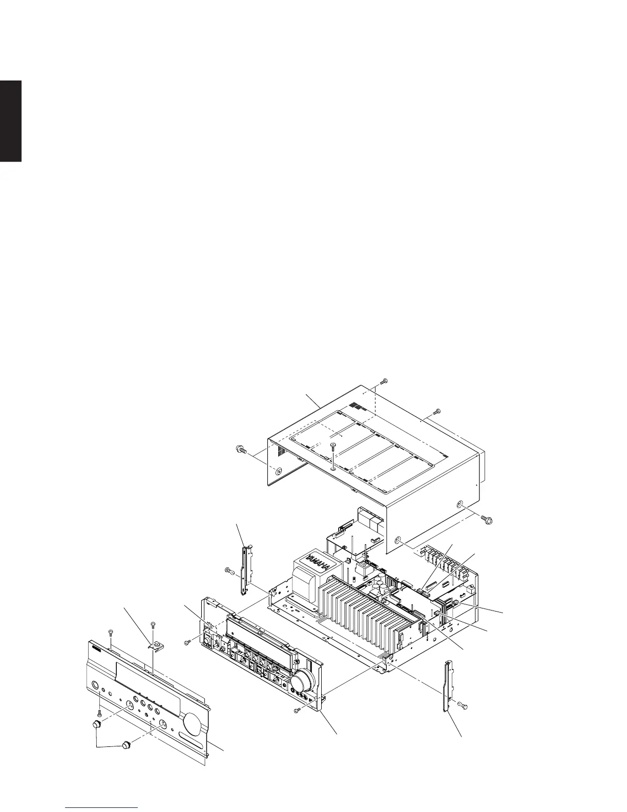
Fig. 1
Sub chassis unit
サブシャーシユニット
Front panel unit
フロントパネルユニット
4
7
7
5
5
Knob
ノブ
Top cover
トップカバー
Plate side L
プレートサイドL
Plate side R
プレートサイドR
1
1
2
3
2
6
6
CB221
CB201
CB46
CB63
CB81
CB452
Support top
サポートトップ
(番号順に部品を取り外してください。)
AC電源コンセントから、電源コードを抜いてください。
1. トップカバーの外し方
a.
1
のネジ4本、
2
のネジ5本、
3
のネジ1本を外しま
す。(Fig.1)
b. トップカバーを後方へスライドさせ、取り外します。
(Fig.1)
2. フロントパネルユニットの外し方
a. ノブを2個取り外します。(Fig.1)
b.
4
のネジ1本を外し、サポートトップを取り外します。
(Fig.1)
c.
5
のネジ6本を外します。(Fig.1)
d. フロントパネルユニットを取り外します。(Fig.1)
3. サブシャーシユニットの外し方
a.
6
のプッシュリベット2本を外します。(Fig.1)
b. プレートサイドL/Rを取り外します。(Fig.1)
c.
7
のネジ2本を外します。(Fig.1)
d. CB46、CB63、CB81、CB201、CB221、CB452を外
します。(Fig.1)
e. サブシャーシユニットを取り外します。(Fig.1)
(Remove parts in the order as numbered.)
Disconnect the power cable from the AC outlet.
1. Removal of Top Cover
a. Remove 4 screws (1), 5 screws (2) and screw (3).
(Fig. 1)
b. Slide the top cover rearward to remove it. (Fig. 1)
2. Removal of Front Panel Unit
a. Remove 2 knobs. (Fig. 1)
b. Remove screw (4) and then remove the support top.
(Fig. 1)
c. Remove 6 screws (5). (Fig. 1)
d. Remove the front panel unit. (Fig. 1)
3. Removal of Sub Chassis Unit
a. Remove 2 push rivets (6). (Fig. 1)
b. Remove the plate side L/R. (Fig. 1)
c. Remove 2 screws (7). (Fig. 1)
d. Remove CB46, CB63, CB81, CB201, CB221 and
CB452. (Fig. 1)
e. Remove the sub chassis unit. (Fig. 1)
■ DISASSEMBLY PROCEDURES/分解手順
 Loading...

