RX-V661/HTR-6060/DSP-AX761
15
9
CB205 CB242 (U, C, R, T, K, A, G, E, L, J models)
CB202 CB232 CB231
FUNCTION (1) P.C.B.
Artbase B
アートベースB
8
DSP P.C.B.
CB206
9
5. DSPP.C.B.の外し方
a.
A
のネジ1本、
B
のプッシュリベット1本を外します。
(Fig.3)
b.
C
のネジ6本を外します。(Fig.4)
c. CB43、CB47、CB62、CB83−85、CB88、CB89を外
します。(Fig.3)
d. DSPP.C.B.を取り外します。(Fig.3)
5. Removal of DSP P.C.B.
a. Remove screw (A) and push rivet (B). (Fig. 3)
b. Remove 7 screws (U, C models) / 6 screws (R, T, K, A,
B, G, E, L models) (C). (Fig. 4)
c. Remove CB43, CB47, CB62, CB83-85, CB88 and
CB89. (Fig. 3)
d. Remove the DSP P.C.B.. (Fig. 3)
F
BD
A
CB89
CB7
CB62
CB88
CB84
CB47
CB301
FUNCTION (5) P.C.B.
FUNCTION (2) P.C.B.
VIDEO P.C.B.
HDMI P.C.B.
Artbase C
アートベースC
CB43
DSP P.C.B.
CB83CB85
U, C, R, T, K, A, B, G, E, L models
J model
RX-V661 (U, C, R, T, K, A, G, E, L models)
HTR-6060 (G model)
DSP-AX761
(B model)
U, C models
0
J
C
H
G
E
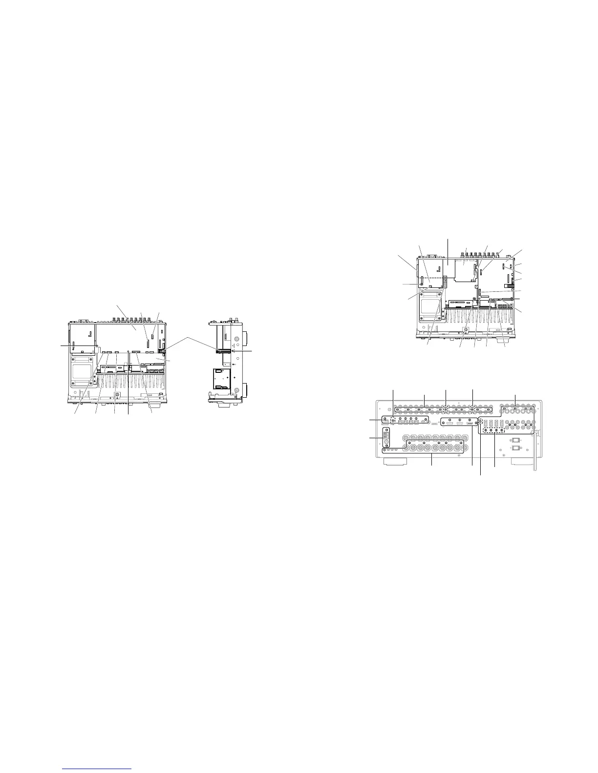
Fig. 3
Fig. 4
Fig. 2
4. FUNCTION(1)P.C.B.の外し方
a.
8
のプッシュリベット1本を外し,アートベースBを取り
外します。(Fig.2)
b.
9
のプッシュリベット2本を外します。(Fig.2)
c.
0
のネジ9本を外します。(Fig.4)
d. CB202、CB205−206、CB231−232、CB242を外し
ます。(Fig.2)
e. FUNCTION(1)P.C.B.を取り外します。(Fig.2)
4. Removal of FUNCTION (1) P.C.B.
a. Remove push rivet (8) and then remove the artbase
B. (Fig. 2)
b. Remove 2 push rivets (9). (Fig. 2)
c. Remove 10 screws (RX-V661: U, C, R, T, K, A, G, E, L
models, HTR-6060: G model, DSP-AX761: B model) /
9 screws (HTR-6060: U, C models) (0). (Fig. 4)
d. Remove CB202, CB205-206, CB231-232 and CB242
(U, C, R, T, K, A, G, E, L models). (Fig. 2)
e. Remove the FUNCTION (1) P.C.B.. (Fig. 2)
 Loading...

