EasyManua.ls Logo

Yamaha DVR-C310 User Manual

Yamaha DVR-C310
40 pages
To Next Page IconTo Next Page
Page #1 background imageLoading...
Page #1 background image
SERVICE MANUAL
This manual has been provided for the use of authorized YAMAHA Retailers and their service personnel.
It has been assumed that basic service procedures inherent to the industry, and more specifically YAMAHA Products, are already
known and understood by the users, and have therefore not been restated.
WARNING: Failure to follow appropriate service and safety procedures when servicing this product may result in personal
injury, destruction of expensive components, and failure of the product to perform as specified. For these reasons,
we advise all YAMAHA product owners that any service required should be performed by an authorized YAMAHA
Retailer or the appointed service representative.
IMPORTANT: The presentation or sale of this manual to any individual or firm does not constitute authorization, certification or
recognition of any applicable technical capabilities, or establish a principle-agent relationship of any form.
The data provided is believed to be accurate and applicable to the unit(s) indicated on the cover. The research, engineering, and service
departments of YAMAHA are continually striving to improve YAMAHA products. Modifications are, therefore, inevitable and
specifications are subject to change without notice or obligation to retrofit. Should any discrepancy appear to exist, please contact the
distributor's Service Division.
WARNING: Static discharges can destroy expensive components. Discharge any static electricity your body may have
accumulated by grounding yourself to the ground buss in the unit (heavy gauge black wires connect to this buss).
IMPORTANT: Turn the unit OFF during disassembly and part replacement. Recheck all work before you apply power to the unit.
IMPORTANT NOTICE
101015
SERVICE MANUAL
INTERNAL VIEW .......................................................... 8
REPAIR NOTES............................................................ 8
DISASSEMBLY PROCEDURES ............................ 9–10
BLOCK DIAGRAM...................................................... 12
WIRING DIAGRAM ..................................................... 13
PRINTED CIRCUIT BOARDS ..............................14–22
SCHEMATIC DIAGRAMS ....................................23–37
REPLACEMENT PARTS LIST.............................38–39
CONTENTS
TO SERVICE PERSONNEL ..................................... 2–3
PREVENTION OF ELECTROSTATIC DISCHARGE ......
4
LOCALE MANAGEMENT INFORMATION ................. 4
SYSTEM COMPOSITION ............................................. 5
FRONT PANEL ............................................................. 5
REAR PANEL ...............................................................6
REMOTE CONTROL PANEL....................................... 6
SPECIFICATIONS..................................................... 6–7
DIMENSIONS ................................................................7
DVX-C310 consists of the DVR-C310 and NX-P300.
DVX-C310SW consists of the DVR-C310 and NX-SW300.
This service manual is for the DVR-C310.
For the NX-P300 and NX-SW300 service manual, please refer to the following publication
number :
DVR-C310
DVD HOME THEATER SOUND SYSTEM
DVX-C310/DVX-C310SW
DVR-C310
DVR-C300/NX-P300 (Including NX-SW300) 100946
© 2006 YAMAHA CORPORATION. All rights reserved.
This manual is copyrighted by YAMAHA and may not be copied or
redistributed either in print or electronically without permission.
’06.07
Question and Answer IconNeed help?

Do you have a question about the Yamaha DVR-C310 and is the answer not in the manual?
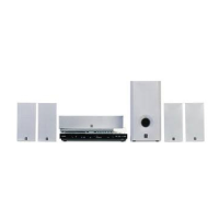
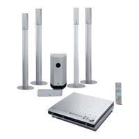
Yamaha DVR-C310 Specifications

General IconGeneral
Video OutputComposite, S-Video, Component
Disc FormatsDVD, DVD-R, DVD-RW, CD, CD-R, CD-RW
AudioDolby Digital
Audio Recording FormatDolby Digital
ConnectionsCoaxial, Analog Audio, Composite Video, Component Video

Summary

Service and Safety Information

To Service Personnel

Information and warnings for authorized service personnel regarding critical components and procedures.

Laser Safety Precautions

Guidelines for safe handling and servicing of the laser pick-up unit to prevent eye damage.

Laser Diode Properties

Prevention of Electrostatic Discharge

Grounding for Electrostatic Damage Prevention

Procedures for grounding worktables and human bodies to prevent ESD damage.

Handling of the Optical Pickup

Precautions for transporting and installing the optical pickup to prevent damage.

Traverse Unit Handling Precautions

Guidelines for gently handling the high-precision traverse unit and its cables.

Locale Management Information

System Composition

Front Panel

Rear Panel

Remote Control Panel

Specifications

General Specifications

Provides technical details like power rating, consumption, and frequency response.

Accessories Included

Lists the items provided with the main unit.

Dimensions

Internal View

Repair Notes

DVD 5-Disc Changer Module

States that the module is supplied as a complete unit and cannot be serviced separately.

PCB Assembly Replacement

Lists PCBs that must be replaced as complete units due to component integration.

Power Supply Unit Precautions

Warns against touching the potentiometer (VR1) on the power supply unit.

Disassembly Procedures

Top Cover Removal

Step-by-step instructions for removing the unit's top cover.

Front Panel Disassembly

Guide for detaching the front panel from the main unit.

DVD 5-Disc Changer Module Removal

Instructions for removing the DVD changer module and its tray assembly.

PCB Removal (General)

General steps for removing various printed circuit boards (MONO, AV, XM, HDMI).

Block Diagram

Wiring Diagram

Printed Circuit Board Layouts

MONO PCB Layouts

Top view of the MONO PCB showing component placement.

AV PCB Layouts

Top view of the AV PCB showing component placement.

Front (1) PCB Layouts

Top and bottom views of the Front (1) PCB showing component locations.

HDMI PCB Layouts

Top view of the HDMI PCB showing component placement.

Schematic Diagrams

MONO Schematic

Detailed circuit diagrams for the MONO PCB, part 1 of 2.

AV Schematic

Detailed circuit diagrams for the AV PCB, part 1 of 6.

Front (1) Schematic

Detailed circuit diagrams for the Front (1) PCB, part 1 of 4.

HDMI Schematic

Detailed circuit diagrams for the HDMI PCB.

XM Schematic

Detailed circuit diagrams for the XM PCB, part 1 of 2.

Replacement Parts List

Overall Assembly Parts

List of part numbers for the main unit's mechanical and electronic components.

Accessory Parts

List of part numbers for included accessories like remote control, antennas, and cables.

Related product manuals