EasyManua.ls Logo

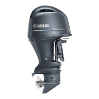
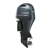
Yamaha F200GET User Manual

Yamaha F200GET
329 pages
To Next Page IconTo Next Page
Page #1 background imageLoading...
Page #1 background image
90894-62983-01Worldwide Edition
RIGGING GUIDE
2014

Table of Contents

Questions and Answers:

Yamaha F200GET Specifications

General IconGeneral
Horsepower200 hp
Compression Ratio10.3:1
Lubrication SystemWet Sump
Starting SystemElectric
Gear Ratio1.75:1
SteeringRemote
Trim & TiltPower Trim & Tilt
Full Throttle RPM Range5000-6000 RPM
Fuel Induction SystemElectronic Fuel Injection (EFI)
ExhaustThrough Propeller
Ignition SystemTCI
Recommended FuelRegular Unleaded
Recommended OilYamalube 4M
Shaft Length25 inches
Engine Type4-Stroke, DOHC, 16-Valve In-Line 4
Displacement2785 cc

Summary

INSTALLATION

UNCRATING PROCEDURE (FOR TYPICAL STEEL FRAME)

Steps for safely removing the outboard motor from its steel crate.

MOUNTING THE OUTBOARD MOTOR

General guidelines and measurement points for mounting the outboard motor.

MOUNTING THE OUTBOARD MOTOR

No strakes hull

Measurement points for mounting on hulls without strakes.

Strakes hull

Measurement points for mounting on hulls with strakes.

PROPELLERS

PROPELLER SELECTION

Guidance on choosing the appropriate propeller.

REMOTE CONTROLS

REMOTE CONTROL TYPES AND APPLICATIONS

Overview of different remote control types and their applications.

DIGITAL ELECTRONIC REMOTE CONTROL WIRE HARNESS

Details on wire harnesses for digital electronic control systems.

TILLER HANDLES

6X4 MULTI-FUNCTION TILLER HANDLE

General introduction to the 6x4 multi-function tiller handle.

MULTI-FUNCTION TILLER HANDLE KIT (FOR US)

Details on the US kit for the multi-function tiller handle.

MULTI-FUNCTION TILLER HANDLE KIT (FOR EU & ANZ)

Details on tiller handle kits for EU & ANZ markets.

WIRING DIAGRAM (FOR EU & ANZ)

Wiring diagrams for EU & ANZ models.

CONVENTIONAL GAUGE (6Y5 & 6Y7)

MOUNTING THE METERS

Procedures for mounting various meters.

ANALOG TACHOMETER

Information on analog tachometers and their applications.

DIGITAL TACHOMETER

Information on digital tachometers and their applications.

SPEEDOMETER

Information on speedometers and their applications.

FUEL MANAGEMENT GAUGE

Information on fuel management gauges and their applications.

ANALOG TRIM METER

Information on analog trim meters and their applications.

COOLANT PRESSURE METER

Information on coolant pressure meters and their applications.

COOLANT TEMP. METER

Information on coolant temperature meters and their applications.

WIRING DIAGRAMS

Overview of wiring diagrams for conventional gauges.

ANALOG TACHOMETER

ANALOG TACHOMETER APPLICATIONS

Applications and applicable models for analog tachometers.

DIGITAL TACHOMETER

DIGITAL TACHOMETER APPLICATIONS

Applications and applicable models for digital tachometers.

POLE NUMBER SET UP

Procedure for setting pole number and other configurations.

SPEEDOMETER

SPEEDOMETER TYPES AND APPLICATIONS

Types and applicable models of speedometers.

DIGITAL SPEEDOMETER SET UP

Procedure for setting up the digital speedometer.

FUEL MANAGEMENT GAUGE

FUEL MANAGEMENT GAUGE TYPES AND APPLICATIONS

Types and applications of fuel management gauges.

FUEL SENSOR INSTALLATION

Instructions for installing the fuel sensor.

WIRING DESCRIPTION

Description of wiring for fuel management gauges.

CONNECTING TO THE DIGITAL SPEEDOMETER (FOR FUEL MANAGEMENT GAUGE)

How to connect the fuel management gauge to the digital speedometer.

CONNECTING TO A GPS

How to connect the fuel management gauge to a GPS unit.

FUEL MANAGEMENT GAUGE SET UP

Procedure for setting up the fuel management gauge.

FUEL MGT GAUGE WITH SPEEDOMETER SET UP

Setup procedure when using with a speedometer.

ANALOG TRIM METER

ANALOG TRIM METER APPLICATIONS

Applications and applicable models for analog trim meters.

TRIM SENSOR ADJUSTMENT

Procedure for adjusting the trim sensor.

COOLANT PRESSURE METER

COOLANT PRESSURE METER APPLICATIONS

Applications and applicable models for coolant pressure meters.

COOLANT PRESS. ATTACHMENT INSTALLATION

Installation method for the coolant pressure attachment.

COOLANT TEMP. METER

COOLANT TEMP. METER TYPES AND APPLICATIONS

Types and applicable models for coolant temperature meters.

ROUTING THE COOLANT TEMP. LEAD & COOLANT PRESS. TUBE

Routing instructions for coolant temp lead and pressure tube.

SENSOR/ATTACHMENT INSTALLATION AND ROUTING

Installation and routing of sensors and attachments.

HOUR METER

WIRING THE MECHANICAL HOUR METER

Wiring diagram for mechanical hour meters.

WIRING THE DIGITAL HOUR METER

Wiring diagram for digital hour meters.

VOLTAGE METER

WIRING THE VOLTAGE METER

Wiring diagram for voltage meters.

FUEL METER

WIRING THE FUEL METER

Wiring diagram for fuel meters.

CHARGE WARNING UNIT

WIRING THE CHARGE WARNING UNIT

Wiring diagram for charge warning units.

WIRE HARNESSES

METER HARNESS

Details on meter harnesses for analog and digital meters.

FUEL MANAGEMENT GAUGE HARNESS

Details on fuel management gauge harnesses.

WIRING DIAGRAMS

WIRE COLOR CODE

Explanation of wire color codes used in wiring diagrams.

DIGITAL METER (6Y5) SINGLE ENGINE APPLICATION 250G

Wiring diagram for single engine 250G models.

DIGITAL METER (6Y5) SINGLE ENGINE w/ SIDE-MOUNT RC

Wiring diagram for single engine with side-mount RC.

DIGITAL METER (6Y5) SINGLE ENGINE w/ BINNACLE RC

Wiring diagram for single engine with binnacle RC.

DIGITAL METER (6Y5) TWIN ENGINE W/ BINNACLE RC

Continues wiring diagram for twin engine with binnacle RC.

ANALOG METER (6Y7) 2-STROKE ENGINES

Wiring diagram for analog meter on 2-stroke engines.

ANALOG METER (6Y7) 2- AND 4-STROKE ENGINES

Wiring diagram for analog meter on 2- and 4-stroke engines.

ANALOG TACHOMETER

Wiring diagrams for analog tachometers.

RIGGING GROMMET DESCRIPTION

F200, F225, F250 (V6-3.3L) w/ Variable Camshaft Timing [Mechanical RC]

Description of rigging grommets for these models.

F200, F225, F250, F275 VMAX (SHO) and F150, F165, F175, F200(L4-2.8L)

Description of rigging grommets for these models.

F200 (L4-2.8L), F225, F250, F300 (V6-4.2L) [DEC]

Description of rigging grommets for these models.

DIGITAL NETWORK GAUGE (6Y8)

NETWORK WIRING DIAGRAMS

Overview of network wiring diagrams.

FUEL INJECTED F30-F250 [Mechanical RC] & HPDI ENGINES

Wiring diagrams for fuel injected and HPDI engines.

TROUBLESHOOTING

Troubleshooting guide for digital network gauges.

DIGITAL NETWORK PREMIUM GAUGE (6Y9)

NETWORK WIRING DIAGRAMS

SINGLE STATION W/ 6Y9 GAUGE SINGLE ENGINE APPLICATION (6X6 binnacle mount Digital Electronic Control)

Wiring diagram for single engine application with 6X6 binnacle mount.

SINGLE STATION W/ 6Y8 GAUGE SINGLE ENGINE APPLICATION (6X6 binnacle mount Digital Electronic Control)

Wiring diagram for single engine application with 6X6 binnacle mount.

SINGLE STATION W/ 6Y9 GAUGE SINGLE ENGINE APPLICATION (6X7 concealed Digital Electronic Control)

Wiring diagram for single engine application with 6X7 concealed control.

SINGLE STATION W/ 6Y8 GAUGE SINGLE ENGINE APPLICATION (6X7 concealed Digital Electronic Control)

Wiring diagram for single engine application with 6X7 concealed control.

SINGLE STATION W/ 6Y9 GAUGE TWIN ENGINE APPLICATION

Wiring diagram for single station, twin engine application.

SINGLE STATION W/ 6Y8 GAUGE TWIN ENGINE APPLICATION

Wiring diagram for single station, twin engine application.

SINGLE STATION W/ 6Y9 GAUGE TRIPLE ENGINE APPLICATION

Wiring diagram for single station, triple engine application.

SINGLE STATION W/ 6Y8 GAUGE TRIPLE ENGINE APPLICATION

Wiring diagram for single station, triple engine application.

DUAL STATION W/ 6Y9 GAUGE SINGLE ENGINE APPLICATION

Wiring diagram for dual station, single engine application.

DUAL STATION W/ 6Y8 GAUGE SINGLE ENGINE APPLICATION

Wiring diagram for dual station, single engine application.

DUAL STATION W/ 6Y9 GAUGE TWIN ENGINE APPLICATION

Wiring diagram for dual station, twin engine application.

DUAL STATION W/ 6Y8 GAUGE TWIN ENGINE APPLICATION

Wiring diagram for dual station, twin engine application.

DUAL STATION W/ 6Y9 GAUGE TRIPLE ENGINE APPLICATION

Wiring diagram for dual station, triple engine application.

BATTERY

RECOMMENDED BATTERY

Guidance on selecting the appropriate battery.

APPENDIX

DIGITAL NETWORK PREMIUM GAUGE RIGGING KIT CONTENTS

Related product manuals