POWR
Power unit
5-53 67C3K11
3. Install the apron and oil dipstick.
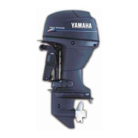
4. Connect the shift link rod 5, and then
install the clip 6.
5. Connect the throttle cable and shift
cable, and then adjust them.
NOTE:
To adjust the throttle cable and shift cable,
see “Adjusting the throttle cable” (3-8) and
“Checking the gear shift operation” (3-9).
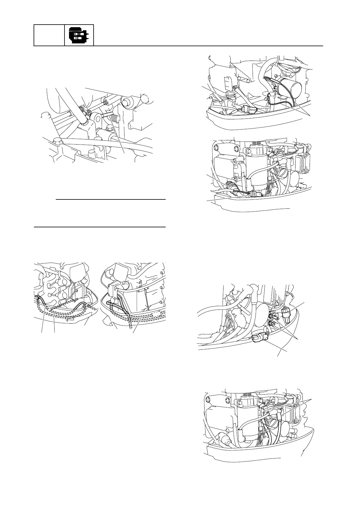
6. Connect the flushing hose 7, cooling
water hose 8, and fuel hose 9.
7. Connect the engine shut-off switch leads
0 and the warning indicator assembly
coupler A. (M model)
Connect the warning indicator assembly
coupler A and 10-pin main harness B to
the power unit. (E and W model)
È M model
É E and W model
8. Connect the PTT motor leads C. (PTT
model)
Connect the PTT switch coupler D and
trim sensor coupler E. (R model with
PTT)
9. Connect the battery cables F. (E and W
model)
S67C5166
6
5
S67C5160
87 9
S67C5167
0
A
È
S67C5168
B
A
É
S67C5169
C
D
E
S67C5170
F