BRKT
Bracket unit
7-9 67C3K11
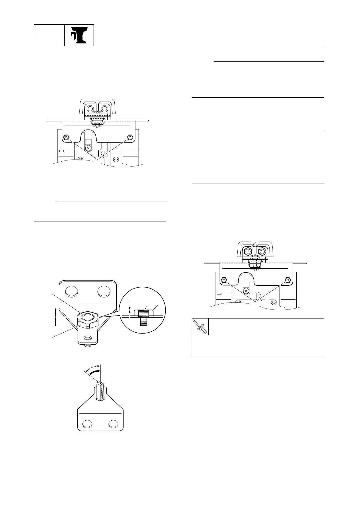
Disassembling the friction plate
1. Remove the tiller handle and friction
plate bolts 1, and then remove the fric-
tion plate assembly from the swivel
bracket.
2. Disassemble the friction plate assembly.
NOTE:
See the exploded diagram for disassembly
(7-8).
Assembling the friction plate
1. Turn the steering lock shaft 1 until it is
flush with the end a of the nut b on the
bracket.
NOTE:
If the steering lock shaft 1 is not aligned with
position c, turn it whichever direction
requires less than 90° d for proper align-
ment.
2. Assemble the friction plate assembly.
NOTE:
• See the exploded diagram for assembly (7-
8).
• Face the “TOP” mark on the steering lock
lever up.
• Be sure to install the collars in the correct
positions; the collar lengths are different.
3. Install the friction plate assembly and
tiller handle, and then tighten the friction
plate bolts 2 and tiller handle nuts 3 to
the specified torque.
4. Move the steering lock lever 4 to posi-
tion e, and then tighten the friction plate
self-locking nut 5 to the specified torque.
S67C7010
1
S67C7011
a
1
a
1
b
b
S67C7012
d
c
T
R
.
.
Friction plate bolt (M6) 2:
8 N·m (0.8 kgf·m, 5.9 ft·lb)
Tiller handle nut 3:
37 N·m (3.7 kgf·m, 27.3 ft·lb)
2
S67C7013