BRKT
Bracket unit
7-7 67C3K11
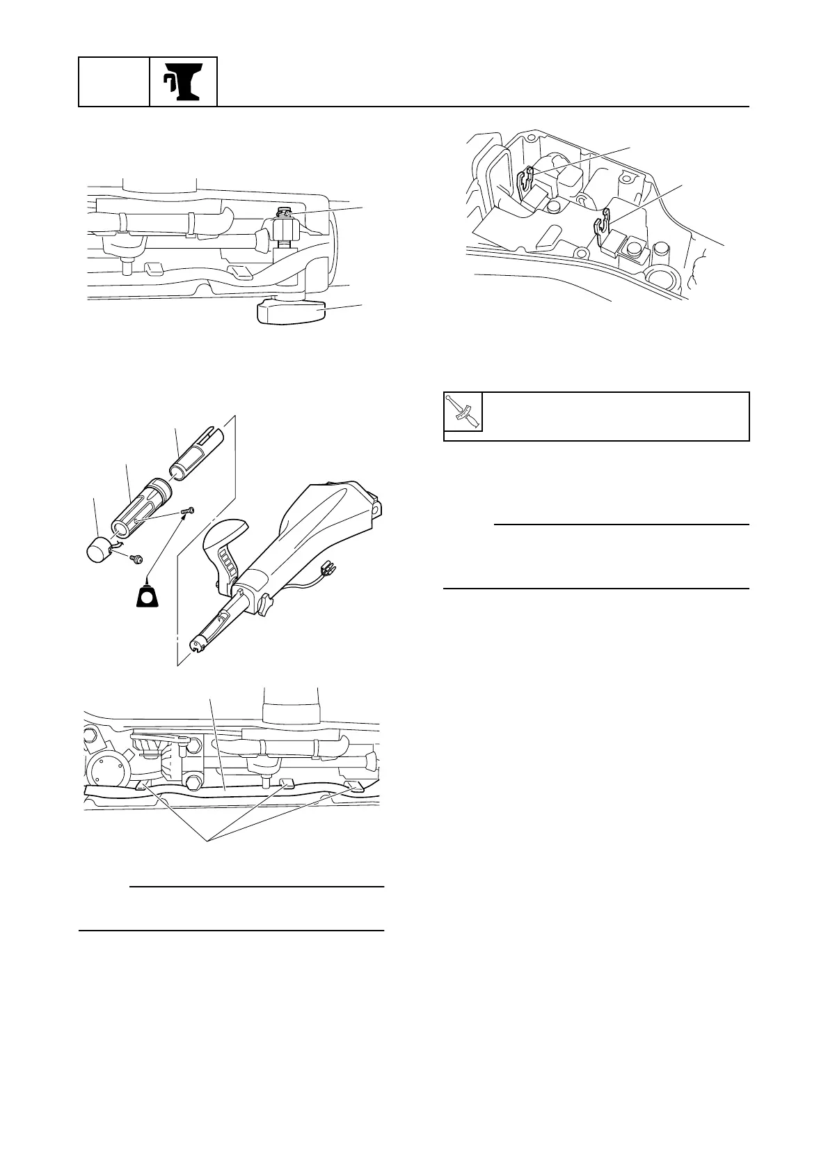
4. Install the throttle friction adjuster 7, and
then install a new cotter pin 8.
5. Install the bushing 9, throttle grip 0,
and PTT switch A (PTT model).
NOTE:
Fasten the PTT switch lead B with the hold-
ers e. (PTT model)
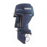
6. Install the throttle cable holder C and
shift cable holder D as shown.
7. Install the tiller handle assembly to the
steering arm, and then tighten the nuts to
the specified torque.
8. Connect the throttle cable and shift
cable.
NOTE:
To adjust the throttle cable and shift cable,
see “Adjusting the throttle cable” (3-8) and
“Checking the gear shift operation” (3-9).
9. Connect the engine shut-off switch leads
(M model), or 10-pin main harness and
warning indicator assembly coupler (E
and W model).
S67C7006
8
7
S67C7007
LT
242
A
0
9
S67C7113
e
B
T
R
.
.
Tiller handle nut:
37 N·m (3.7 kgf·m, 27.3 ft·lb)
S67C7114
D
C
 Loading...