IGNITION SYSTEM (For Drum)
6-3
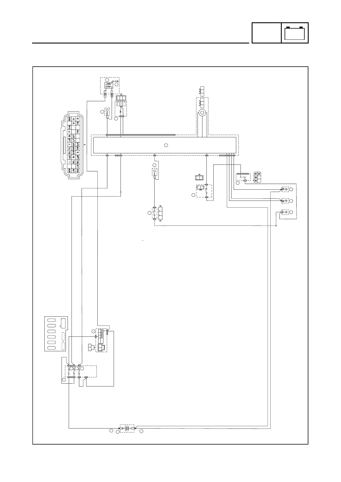
IGNITION SYSTEM (For Drum)
CIRCUIT DIAGRAM
R
R/B
Br
Br
Br
15A
2A
7.5A
R/B
R/B
Br
R/B
05
06
07
04
Or
Br
W/R W/R
Or Or
Or
W/L W/L
19
20
21
22
27
18
34
B
B
L/Y
B
L
L/Y
B
28
B/W
B
BB
BB
B
B
64
63
65
B
B
62
R
01
02
03
R/B
Br
Br
R/B
Br
R
OFF
ON
Br/B
R/B
Br
R/B R/B
Br
R/B
Y/B
Y/B
Y/B
L/Y
B
B
B
B/W
Y/B B
B
Y/B
BB
Gy P/Y
G/LB/L B
Br
Br
Br Br/ B R/B
Br/L,Br Br R/B
R
R/B
SPARE SPARE
B
7.5A
2A
7.5A
2A
2A
15A
15A 7.5A
10
W/R
W/L
W/R
W/L
L
W
Y
Br
R
B
33
B7JF8197E1.book Page 3 Tuesday, June 29, 2021 2:28 PM
1. Battery
2. Battery positive lead
3. Battery negative lead
4. Fuse box
5. Main fuse
6. Backup fuse
7. Sub fuse
10.Main switch
18.SGCU (Starter generator control unit)
19.Joint connection 2
20.Ignition coil
21.Spark plug
22.Crankshaft position sensor
27.Starter generator
28.Sidestand switch
33.Joint connection 4
34.Stop and start system switch
62.Junction (Ground)
63.Engine ground 1
64.Engine ground 2
65.Engine ground 3
 Loading...