19
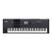
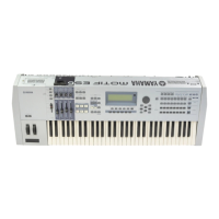
MOTIF XS6/MOTIF XS7/MOTIF XS8
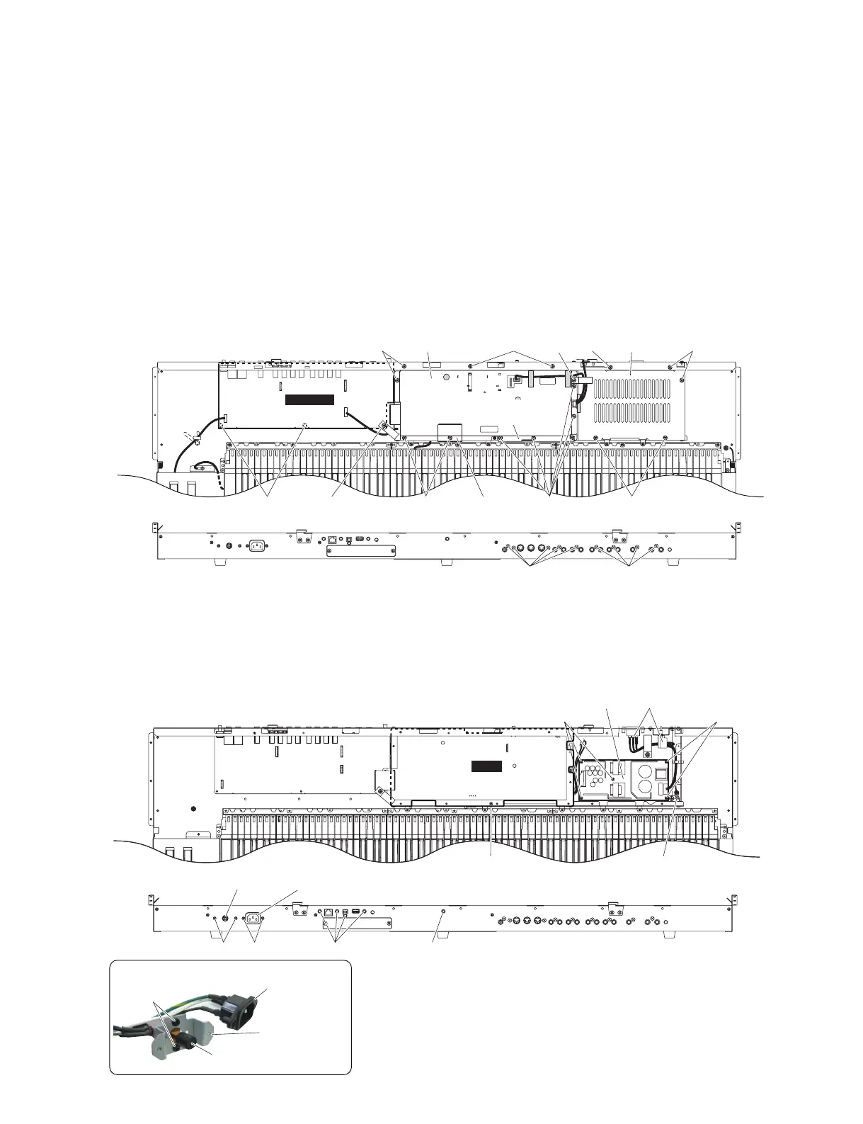
<Top view>
<Rear view>
JKAN-JA
[390] [385] [350] [270][350]
[350]
DM cover
(カバーDM)
DM earth plate
(DMアースプレート)
Earth plate B
(アースプレートB)
PS guard
(ガードPS)
[270][270][267]
[370] [370]
[350]
DM
<Top view>
[320] [210]
(電源ユニット)
Power supply unit
[230][230]
[200] [200] [310]
(ACIN束線)
AC IN connector assembly
(ACインレット)
AC-IN connector
(電源スイッチ)
Power switch
<Rear view>
[310]
(ACインレット)
AC-IN connector
(電源スイッチ)
Power switch
[190]
(PSWアングル)
Power switch holder
• AC IN connector assembly(ACIN束線)
* This fi gure shows the MOTIF XS7.(この図は MOTIFXS7 です。)
* This fi gure shows the MOTIF XS7.(この図は MOTIFXS7 です。)
Fig.4( 図 4)
[267]:CupScrew-B(B タイト+ CUP)3.0X8MFZN2W3(WK386600)
[270]:BindHeadTappingScrew-B(B タイト+ BIND)3.0X6MFZN2W3(WE936300)
[350]:BindHeadTappingScrew-B(B タイト+ BIND)3.0X6MFZN2W3(WE936300)
[370]:BindHeadTappingScrew-B(B タイト+ BIND)3.0X10MFZN2B3(WE972200)
[385]:CupScrew-B(B タイト+ CUP)3.0X8MFZN2W3(WK386600)
[390]:BindHeadTappingScrew-B(B タイト+ BIND)3.0X6MFZN2W3(WE936300)
Fig.5( 図 5)
[190]:BindHeadScrew(小ネジ+ BIND)3.0X6MFZN2B3(WE878300)
[200]:BindHeadTappingScrew-B(B タイト+ BIND)3.0X10MFZN2B3(WE972200)
[210]:BindHeadTappingScrew-S(S タイト+ BIND)4.0X8MFZN2W3(WE941800)
[230]:BindHeadTappingScrew-B(B タイト+ BIND)3.0X6MFZN2W3(WE936300)
[310]:BindHeadScrew(小ネジ+ BIND)3.0X6MFZN2B3(WE878300)
[320]:BindHeadTappingScrew-B(B タイト+ BIND)3.0X6MFZN2W3(WE936300)
4-4 [350] のネジ 11 本を外して、カバー DM とアース
プレート B、DM アースプレートを外します。(図 4)
4-5 [310] の ネ ジ 5 本 と [320] の ネ ジ 1 本 を 外 し て、
DM シートを外します。(図 5)
※ DM シートを交換するときに、CN705 と CN706
に拡張基板が差し込まれていれば、DM シートか
ら拡張基板を外してから交換してください。
※ DM シートを交換した場合は MACAddress の書
き込みを行ってください。詳しくは 140 ページを
参照してください。
4-4 Remove the eleven (11) screws marked [350]. The
DM cover, earth plate B and DM earth plate can
then be removed. (Fig. 4)
4-5 Remove the fi ve (5) screws marked [310] and the
screw marked [320]. The DM circuit board can
then be removed. (Fig. 5)
* If you find extension circuit boards attached
to the CN705 and CN706 when replacing the
DM circuit board, remove the extension circuit
boards from the DM circuit board and then re-
place the DM circuit board.
* If you replaced the DM circuit board, execute
MAC Address writing. See page 113 for details.

 Loading...