41
MOTIF XS6/MOTIF XS7/MOTIF XS8
[30]: Push button, x1 M (Black)
( プッシュボタン (M)( 黒 ))
[40]: Push button, x3 MR (Gray)
( プッシュボタン (MR)( 灰 ))
[80]: Push button, x4 MR (Gray)
( プッシュボタン (MR)( 灰 ))
[50]: Push button, x2 MR (Gray)
( プッシュボタン (MR)( 灰 ))
[60]: Push button, x1 MR (Gray)
( プッシュボタン (MR)( 灰 ))
[90]: Push button, x4 MR (Black)
( プッシュボタン (MR)( 黒 ))
[60]: Push button, x1 MR (Gray)
( プッシュボタン (MR)( 灰 ))
[70]: Push button, x2 M (Gray)
( プッシュボタン (M)( 灰 ))
[20]: Push button, x1 M (Gray)
( プッシュボタン (M)( 灰 ))
[20]: Push button, x1 M (Gray)
( プッシュボタン (M)( 灰 ))
[60]: Push button, x1 MR (Gray)
( プッシュボタン (MR)( 灰 ))
• PNC circuit board
(PNC シート)
Encoder knob
(エンコーダーツマミ)
11. PNC Circuit Board
(Time required: About 6 minutes)
11-1 Remove the encoder knob. (Fig. 8, 11)
11-2
Remove the side cover R and side cover L. (See procedure 1.)
11-3
Remove the control panel assembly. (See procedure 2.)
11-4 Remove the EMC cover. (See procedure 7-3.)
11-5 Remove the two (2) each screws marked [110].
The two (2) PCB angles 1 (B) can then be re-
moved. (Fig. 8)
11-6 Remove the five (5) screws marked [90B]. The
PNC circuit board can then be removed. (Fig. 10)
* When installing the PNC circuit board, fit the
holes to the positioning pins C fi rst, and then
tighten the screws. (Fig. 10)
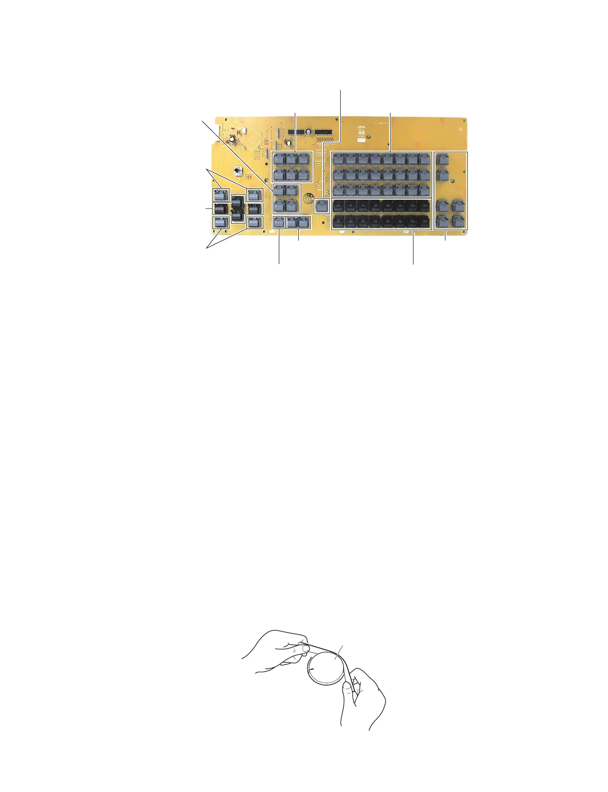
* The PNC circuit board contains the following
buttons. (Photo 5)
• [20]: Push button, M (Gray) 4 pcs.
• [30]: Push button, M (Black) 4 pcs.
• [40]: Push button, MR (Gray) 2 pcs.
• [50]: Push button, MR (Gray) 2 pcs.
• [60]: Push button, MR (Gray) 8 pcs.
• [70]: Push button, M (Gray) 1 pc.
• [80]: Push button, MR (Gray) 6 pcs.
• [90]: Push button, MR (Black) 4 pcs.
11. PNC シート(所要時間:約 6 分)
11-1 エンコーダーツマミを外します。(図 8、図 11)
11-2 腕木 R と腕木 L を外します。(1 項参照)
11-3 コンパネ Assy を外します。(2 項参照)
11-4 EMC カバーを外します。(7-3 項参照)
11-5 [110] のネジ 2 本ずつを外して、PCB アングル 1B
を 2 個外します。(図 8)
11-6 [90B] のネジ 5 本を外して、PNC シートを外しま
す。(図 10)
※ PNC シートを取り付けるときは、位置決めピン C
に差し込んでからネジ止めしてください。(図 10)
※ PNC シートには下記のボタンがついています。
(写真 5)
・[20]:プッシュボタン (M)( 灰 ) 4 個
・[30]:プッシュボタン (M)( 黒 ) 4 個
・[40]:プッシュボタン (MR)( 灰 ) 2 個
・[50]:プッシュボタン (MR)( 灰 ) 2 個
・[60]:プッシュボタン (MR)( 灰 ) 8 個
・[70]:プッシュボタン (M)( 灰 ) 1 個
・[80]:プッシュボタン (MR)( 灰 ) 6 個
・[90]:プッシュボタン (MR)( 黒 ) 4 個
Photo5( 写真 5)
Fig.11( 図 11)

 Loading...