4
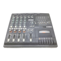
Chapter 2: Getting to Know the MT50
MT50 User’s Guide
1
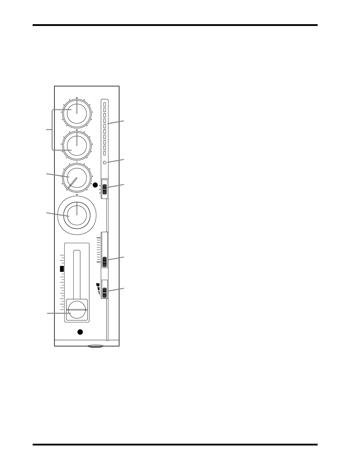
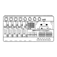
HIGH and LOW equalization controls:
These controls
adjust the tone (EQ). When something is connected to the
MIC/LINE input, these controls affect the tone of the input signal
(i.e., the signal to be recorded). When nothing is connected to the
MIC/LINE input, these controls affect the tone of the playback
signal (i.e., the tape signal fed into the stereo mix).
2
AUX control:
This control sets the level of the signal fed to the
AUX SEND output, which is used to feed an external effects pro-
cessor. The MT50’s aux send signal is sourced after the fader. To
feed a channel’s signal to an external effects processor via the aux
send, you must turn up its AUX control and raise its fader.
3
PAN control:
This control positions the playback of a sound in
the stereo mix (i.e., between the left and right channels). Turning
to the right pans a signal to the right channel; turning to the left
pans a signal to the left channel. For center position, an equal
amount of signal is fed to both the left and right outputs.
4
Fader:
When something is connected to the MIC/LINE input,
the fader sets the recording level (i.e., the level of the input signal
recorded to tape). When nothing is connected to the MIC/LINE
input, this fader sets the playback level (i.e., the level of the tape
signal fed to the stereo mix). For best performance, the fader
should be positioned between 7 and 8.
5
Level meter:
This LED meter shows the recording and play-
back level. The recording level should be set so that the +6 LED
lights occasionally at the maximum input level. The fader sets the
recording level.
6
REC indicator:
This indicator shows the recording mode.
Off
— REC SEL switch set to OFF.
Flashing
— REC SEL switch set to one of the “on” positions (i.e.,
set to 1, 2, 3, 4, L, or R, in which case the track is ready to record).
Lit
— Recording in progress or recording paused.
7
REC SEL switch:
This switch selects the signal to be recorded.
Off
— Recording is not active.
1 (2, 3, 4)
— The MIC/LINE input signal is recorded.
L (R)
— The left (right) stereo mix signal is recorded. Left signals
can be recorded to tracks 1 and 3. Right signals can be recorded to
tracks 2 and 4. Use this setting for ping-pong recording.
8
CUE slider:
This control sets the CUE level. CUE allows you to
adjust the volume of the monitor independently of the fader set-
tings. This control is effective only when the MONITOR
SELECT switch is set to either MIX or CUE.
9
GAIN switch:
This switch sets the MIC/LINE input gain for
optimum performance, depending on what you connect to the
MIC/LINE input.
MIC
— microphones, low-level devices.
Middle
— electric guitar, electric bass.
LINE
— synthesizer, drum machine, CD player, high-level devices.
! For the technically minded, the
HIGH control has a center fre-
quency of 12kHz and the LOW con-
trol, 80Hz. Both controls offer up to
12dB of cut and boost.
Note: Controls 1 through 9 are the
same for all four input modules.
–+
–+
HIGH
LOW
AUX
PAN
1
OFF
L
REC
SEL
LR
010
CUE
10
0
MIC/LINE
10
9
8
7
6
5
4
3
2
1
0
+6
+3
0
-5
-10
REC
1
GAIN
MIC
LINE
1
9
8
7
6
5
4
3
2