PC9501N
9
■ DISASSEMBLY PROCEDURE(分解手順)
1. Top Cover (Time required: about 2 minutes)
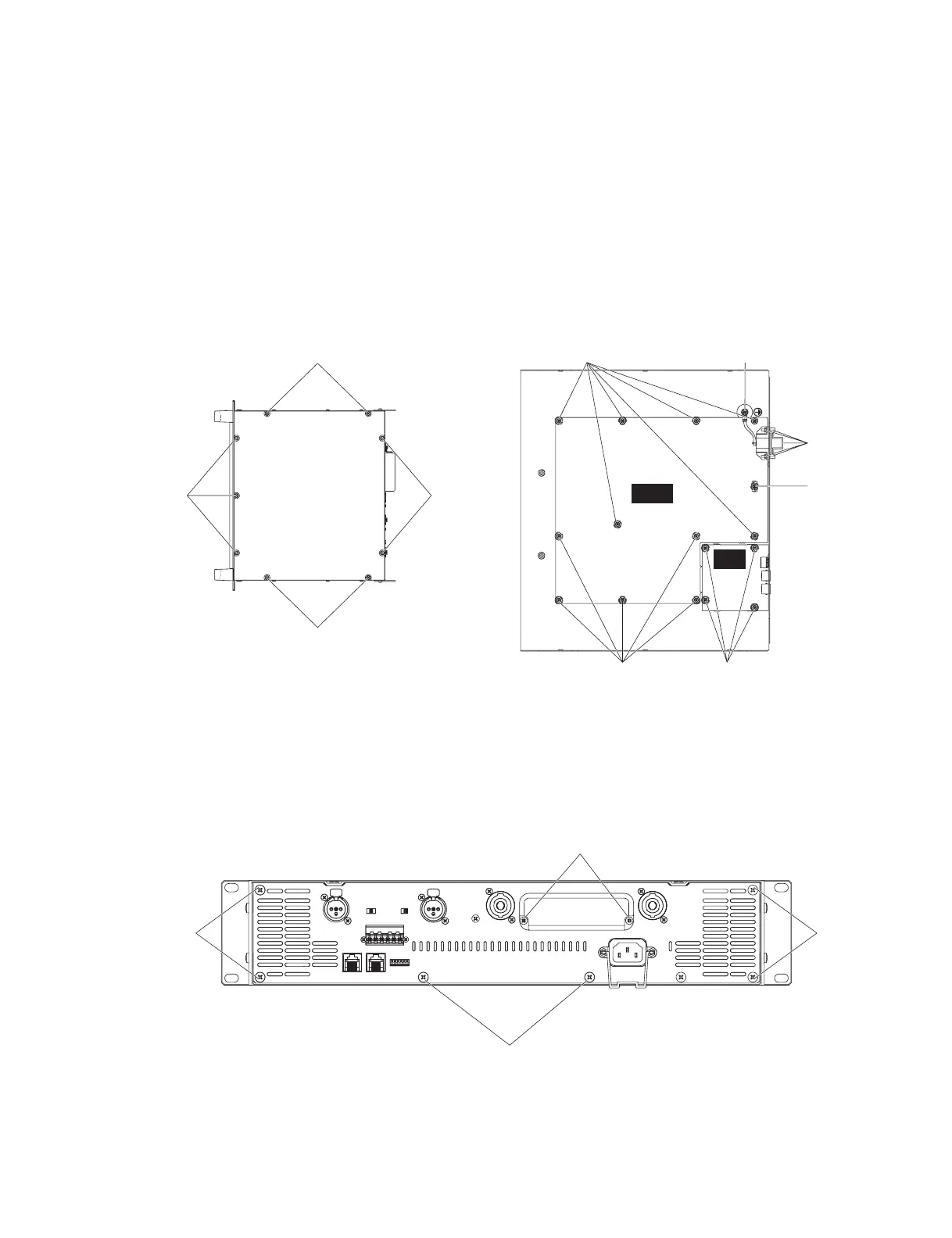
1-1. Remove the nine (9) screws marked [280]. The top
cover can then be removed. (Fig. 1)
2. Rear Assembly (Time required: about 4 minutes)
2-1. Remove the top cover. (See Procedure 1.)
2-2. Remove the six (6) screws marked [240]. The rear
assembly can then be removed. (Fig. 2)
∗
With PC9501N of the J specification, remove the screw
marked [90]. (Fig.1)
1. トップカバー(所要時間:約 2 分)
1-1. [280] のネジ 9 本を外 し、 ト ッ プカバーを外 し ます。
(図1)
2. リア Assy(所要時間:約 4 分)
2-1. ト ッ プカバーを外 し ます。 (1 項参照 )
2-2. [240] のネジ 6 本を外 し、 リ ア Ass’ y を外 し ます。(図 2)
∗
PC9501N(J) 仕向は [90]のネジを外します。( 図 1)
[30]: Bind Head Tapping Screw-B 3.0X8 MFZN2BL (EP600190)+ バインド B タイト
[90]: Bind Head Screw 4.0X8 MFZN2BL (EG340360) + バインド小ネジ
[100]: Bind Head Tapping Screw-B 3.0X8 MFZN2BL (EP600190) + バインド B タイト
[280]: Bonding Tapping Screw-B 4.0X8 MFZN2BL (VR779900) ボンディング B タイト
Fig.1 (図 1)
[240]: Bonding Tapping Screw-B 4.0X8 MFZN2BL (VR779900) ボンディング B タイト
[330]: Bind Head Tapping Screw-B 3.0X8 MFZN2BL (EP600190) + バインド B タイト
Fig.2 (図 2)
[280] [280]
[280]
[280]
[100]
[30b]
[30b]
[40]
[90]
[30a]
PS10 1/2
IN10
4/5
I/O rock
[240][240]
[330]
[240]


 To Next Page