Periodic maintenance and adjustment
7-26
7
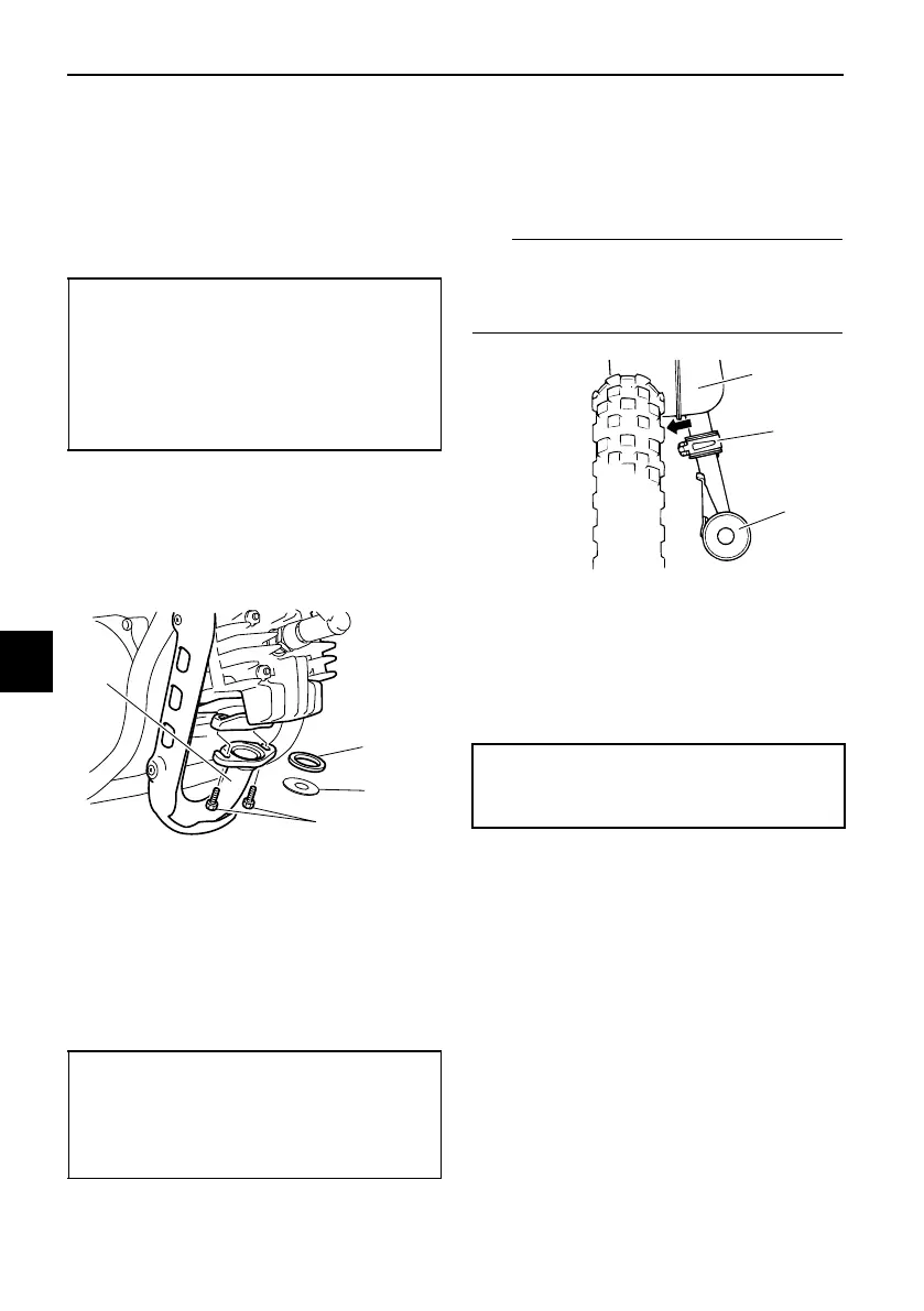
6. While applying the rear brake,
tighten the axle nut to the speci-
fied torque.
7. Tighten the rear arm nuts and rear
shock absorber mounting bolt to
the specified torques.
8. Install the exhaust chamber by in-
stalling the bolt and washers.
9. Install the power reduction plate, a
new gasket, and then install the
exhaust manifold bolts.
10. Tighten the exhaust manifold bolts
and exhaust chamber bolt to the
specified torques.
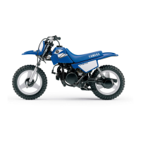
11. Install the muffler by sliding the
spring clamp up to its original po-
sition, and then installing the
washers and muffler bolt.
Make sure that the spring clamp is po-
sitioned with the projection side facing
inward.
12. Tighten the muffler bolt to the
specified torque.
13. Adjust the brake lever free play.
(See page 7-17.)
14. Install the seat.
Tightening torques:
Axle nut:
60 N·m (6.0 kgf·m, 44 lb·ft)
Rear arm nut:
29 N·m (2.9 kgf·m, 21 lb·ft)
Rear shock absorber mounting bolt:
23 N·m (2.3 kgf·m, 17 lb·ft)
1. Exhaust manifold
2. Gasket
3. Power reduction plate
4. Exhaust manifold bolt
Tightening torques:
Exhaust manifold bolt:
9 N·m (0.9 kgf·m, 6.6 lb·ft)
Exhaust chamber bolt:
18 N·m (1.8 kgf·m, 13 lb·ft)
1. Exhaust chamber
2. Spring clamp
3. Muffler
Tightening torque:
Muffler bolt:
18 N·m (1.8 kgf·m, 13 lb·ft)
U2SA14E0.book Page 26 Monday, May 1, 2017 10:19 AM