Do you have a question about the Yamaha RDX-E600 and is the answer not in the manual?
| Number of Channels | 2 |
|---|---|
| Frequency Response | 20 Hz - 20 kHz |
| Signal-to-Noise Ratio | 80 dB |
| Bluetooth | No |
| Disc Formats | CD, CD-R, CD-RW |
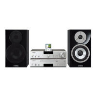
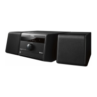
| Speakers | 2-way bass reflex speakers |
| CD Player | Yes |
| Inputs | USB, AUX |
| Tuner Bands | FM |
| Preset Stations | 30 |
| Connectivity | USB, AUX |
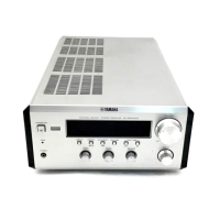
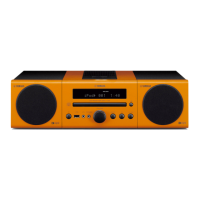
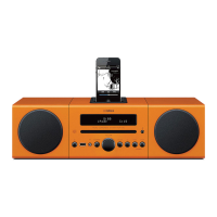
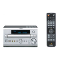
| Type | Micro Component System |
Procedure for measuring AC leakage current to ensure proper insulation.
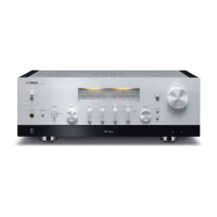
Detailed technical specifications for the RX-E600 audio and AM sections.
Step-by-step guide for disassembling the unit, including top cover and front panel removal.
Instructions for entering and operating the unit's test modes.
Procedures for adjusting amplifier bias and confirming idling current.
Steps to measure and confirm the idling current for amplifier channels.
Comprehensive pinout and function data for the M30218FCFP microcomputer IC.
Detailed list of ports, names, directions, and functions for IC700.
Overall system block diagram illustrating component interconnections.
Foil side views of OPERATION (1) and (2) PCBs, including semiconductor locations.
Main circuit schematic diagram showing the interconnections of major blocks.
Circuit schematic diagram for the operation section, including CPU and related components.
Schematic diagram and features of the remote control system.
Explains system operation, including power on/off, function selection, and timer functions.
Detailed sequence for powering units on and off.
How timer play is executed, including power-on and command transmission.
How timer recording is executed, including power-on and command transmission.
Execution flow for timer play with status communication.
Table detailing commands, codes, and data for system control bus communication.
Table of system control bus data codes for functions, dimmer, and edit operations.