8-30
1FSJPEJDNBJOUFOBODFBOEBEKVTUNFOU
EAU78242
3FQMBDJOHUIFGVTFT
The main fuse and the fuse boxes,
which contain the fuses for the individ-
ual circuits, are located under panel A.
(See page 8-8.)
5*1
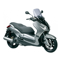
To access the main fuse, remove the
starter relay cover as shown.
1. Fuse box
2. Main fuse
3. Spare main fuse
4. Starter relay cover
1
2
3
4
If a fuse is blown, replace it as follows.
1. Turn the main switch off and turn
off the electrical circuit in ques-
tion.
2. Remove the blown fuse, and then
install a new fuse of the specied
amperage. 8"3/*/( %P OPU
VTFBGVTFPGBIJHIFSBNQFSBHF
SBUJOH UIBO SFDPNNFOEFE UP
BWPJE DBVTJOH FYUFOTJWF EBN
BHFUPUIFFMFDUSJDBMTZTUFNBOE
QPTTJCMZBãSF
[EWA15132]
3. Turn the main switch on and turn
on the electrical circuit in question
to check if the device operates.
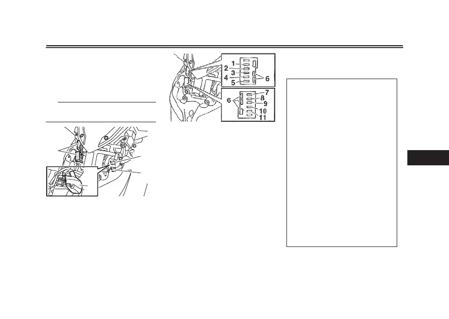
1. Signaling system fuse
2. ABS control unit fuse
3. Main fuse 2
4. Radiator fan motor fuse
5. Backup fuse
6. Spare fuse
7. ABS motor fuse
8. ABS solenoid fuse
9. Turn signal light and hazard fuse
10. Terminal fuse 1
11. Answer back fuse
4QFDJãFEGVTFT
Main fuse:
20.0 A
Main fuse 2:
7.5 A
Terminal fuse 1:
2.0 A
Signaling system fuse:
10.0 A
Signaling system fuse 2:
7.5 A
Radiator fan motor fuse:
7.5 A
Backup fuse:
7.5 A
Turn signal light and hazard fuse:
7.5 A
ABS control unit fuse:
7.5 A
ABS motor fuse:
30.0 A
ABS solenoid fuse:
15.0 A
Answer back
fuse:
2.0 A