*OTUSVNFOUBOEDPOUSPMGVODUJPOT
5-23
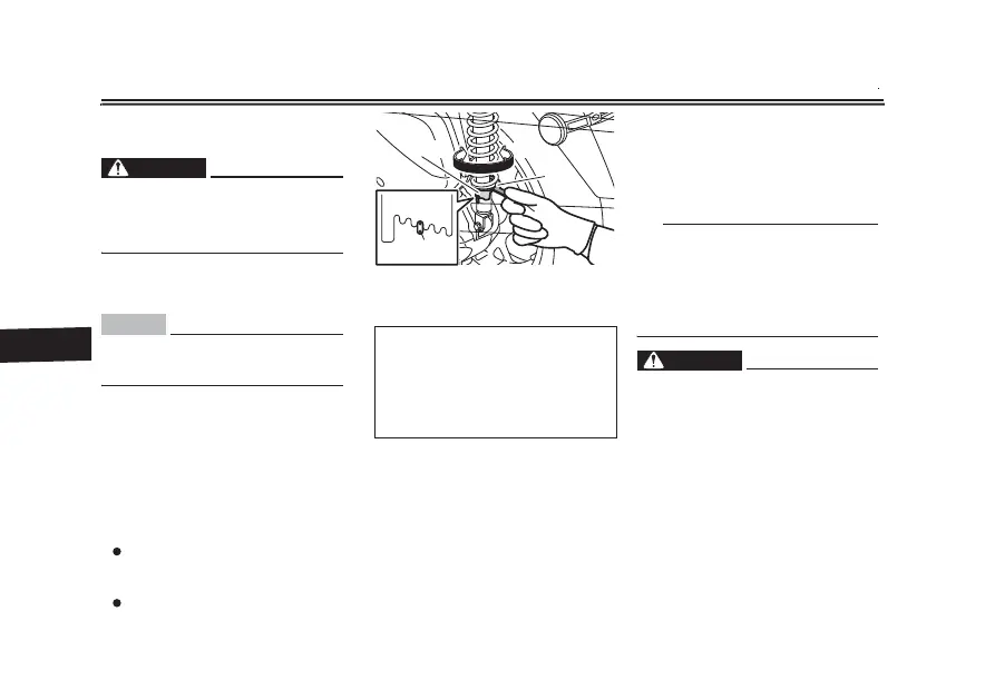
EAU14893
"EKVTUJOHUIFTIPDLBCTPSCFS
BTTFNCMJFT
8"3/*/(
EWA10211
"MXBZTBEKVTUCPUI TIPDLBCTPSCFS
BTTFNCMJFTFRVBMMZPUIFSXJTF QPPS
IBOEMJOHBOEMPTTPGTUBCJMJUZNBZSF
TVMU
Each shock absorber assembly is
equipped with a spring preload adjust-
ing ring.
NOTICE
ECA10102
5PBWPJEEBNBHJOHUIFNFDIBOJTN
EP OPU BUUFNQU UP UVSO CFZPOE UIF
NBYJNVNPSNJOJNVNTFUUJOHT
Adjust the spring preload as follows.
To increase the spring preload and
thereby harden the suspension, turn
the adjusting ring on each shock ab-
sorber assembly in direction (a). To de-
crease the spring preload and thereby
soften the suspension, turn the adjust-
ing ring on each shock absorber as-
sembly in direction (b).
Align the appropriate notch in the
adjusting ring with the position in-
dicator on the shock absorber.
Use the spring preload adjusting
tool included in the owner’s tool
kit to make this adjustment.
EAU15306
4JEFTUBOE
The sidestand is located on the left
side of the frame. Raise the sidestand
or lower it with your foot while holding
the vehicle upright.
5*1
The built-in sidestand switch is part of
the ignition circuit cut-off system,
which cuts the ignition in certain situa-
tions. (See the following section for an
explanation of the ignition circuit cut-
off system.)
8"3/*/(
EWA10242
5IFWFIJDMFNVTUOPUCFSJEEFOXJUI
UIF TJEFTUBOE EPXO PS JG UIF TJEF
TUBOEDBOOPUCFQSPQFSMZNPWFEVQ
PSEPFTOPUTUBZVQPUIFSXJTFUIF
TJEFTUBOEDPVMEDPOUBDUUIFHSPVOE
BOE EJTUSBDU UIF PQFSBUPS SFTVMUJOH
JO B QPTTJCMF MPTT PG DPOUSPM
:BNBIBT JHOJUJPO DJSDVJU DVUPGG
TZTUFNIBTCFFOEFTJHOFEUPBTTJTU
UIFPQFSBUPSJOGVMãMMJOHUIFSFTQPO
TJCJMJUZ PG SBJTJOH UIF TJEFTUBOE CF
GPSF TUBSUJOH PGG 5IFSFGPSF DIFDL
1. Spring preload adjusting ring
2. Special wrench
3. Position in
dicator
4QSJOHQSFMPBETFUUJOH
Minimum (soft):
1
Standard:
3
Maximum (hard):
5
1
2
3
4
5
2
1
(a) (b)
3