EasyManua.ls Logo

Yamaha XP5000 - User Manual

Yamaha XP5000
22 pages
Print Icon
To Next Page IconTo Next Page
Loading...
POWER AMPLIFIER
OWNER’S MANUAL
BEDIENUNGSANLEITUNG
MODE D’EMPLOI
MANUAL DE INSTRUCCIONES
ES
FR
DE
EN
EnglishDeutschFrançaisEspañol

Questions and Answers

  • E
    Edward WestAug 8, 2025
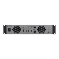
    Why is the PROTECTION indicator lighting up on my Yamaha XP5000 Amplifier?
    • P
      Patricia VelezAug 8, 2025
      The PROTECTION indicator on your Yamaha Amplifier lights up because the heat sink temperature has exceeded 90°C (194°F). Check the amplifier ventilation conditions and take appropriate measures to improve the airflow around the amplifier.
  • O
    ojacksonAug 18, 2025
    What to do if the CLIP indicator lights on my Yamaha XP5000 are on?
    • S
      Susan OwensAug 18, 2025
      If the CLIP indicator lights are illuminated on your Yamaha Amplifier, it indicates a short circuit at a speaker terminal, amplifier terminal, or wire. Locate and correct the cause of the short. It can also mean that the amplifier load is excessive. Use a speaker system with an impedance of at least 4 ? in STEREO/PARALLEL mode or 8 ? in BRIDGE mode.
  • W
    William StevensAug 27, 2025
    How to fix TEMP indicator lights on Yamaha XP5000 Amplifier?
    • L
      lisabryantAug 27, 2025
      If the TEMP indicator lights are on, it means the heat sink temperature has exceeded 85°C (185°F). Check the ventilation slots, and provide better airflow around the amplifier.

Summary

Safety and Compliance Information

FCC Notices

Important warnings regarding FCC compliance, product modification, and cable usage.

Graphical Symbol Explanations

Explains the meaning of safety symbols such as danger and caution used in the manual.

General Safety Instructions

Essential precautions for safe operation, installation, and maintenance of the amplifier.

Precautions

Warnings and Cautions

Detailed warnings and cautions regarding power, location, connections, and maintenance.

Handling Cautions

Safe Handling Practices

Guidelines for safe operation, avoiding damage, and preventing hearing loss.

Introduction

Product Overview and Features

Overview of the XP Series power amplifiers, highlighting key features and development.

Front Panel Controls and Indicators

Front Panel Layout

Detailed description of the controls and indicators on the front panel.

Rear Panel Layout

Connectors and Switches

Detailed description of the rear panel connectors, switches, and terminals.

Speaker Connections

Stereo Mode Connection

Connecting speakers in Stereo mode via binding posts or Speakon connectors.

Parallel Mode Connection

Connecting speakers in Parallel mode via binding posts or Speakon connectors.

Bridged Mode Operation

High-Power Mono Connection

Connecting speakers in Bridged mode for high-power mono operation.

High-Impedance Speaker Connections (XP7000;3500)

XP7000 70 V Line Output

Detailed connection guide for high-impedance speakers using the XP7000's 70V line output.

XP3500 100 V Line Output

Detailed connection guide for high-impedance speakers using the XP3500's 100V line output.

Connection Methods

Using a Euroblock Connector

Instructions for connecting audio sources using Euroblock connectors.

Speaker Connection Details

Detailed steps for connecting speakers via 5-way binding posts and Speakon connectors.

Troubleshooting

Indicator Lights and Solutions

Diagnosing and resolving common operational issues indicated by LED lights.

Specifications

General Specifications

Comprehensive technical data covering output power, SN ratio, and power consumption for all models.

Detailed Specifications

Performance and Electrical Data

In-depth technical data including bandwidth, frequency response, input sensitivity, and impedance.

MONITOR;REMOTE Terminal Layout

Pin Configuration and Function

Details of the MONITOR/REMOTE terminal pin assignments and their functions.

Dimensions

Physical Dimensions Diagram

Diagram and specific measurements of the amplifier's physical size.

Block Diagram

XP7000;XP5000 Internal Structure

Diagram illustrating the internal signal flow and electronic components of the XP7000 and XP5000.

XP3500;XP2500;XP1000 Block Diagram

Internal Circuitry Overview

Diagram illustrating the internal signal flow and electronic components of the XP3500, XP2500, and XP1000.

Current Draw and Power Consumption

Power Usage Details

Tables detailing line current, power consumption, and thermal dissipation for each model.

Yamaha Contact Information

Worldwide Distributor Network

Contact details for Yamaha representatives and authorized distributors in various regions.

Yamaha XP5000 Specifications

General IconGeneral
Frequency Response20 Hz - 20 kHz
Total Harmonic Distortion (THD)≤ 0.1%
Input Impedance20 kΩ
ConnectorsXLR
Dimensions (W x H x D)19.0 x 3.5 x 16.5 inches
Dimensions19.0 x 3.5 x 16.5 inches

Related product manuals