下記の部品を交換した場合、本機が正常に動作するため
にシステムモデル名と仕向け先を EEPROM に書き込む必
要があります。
・ DIGITALP.C.B.
・ DIGITALP.C.B. の EEPROM(IC703)
When the following parts are replaced, the system
model name and the destination MUST be written to the
EEPROM to have proper operation.
• DIGITAL P.C.B.
• EEPROM (IC703) on DIGITAL P.C.B.
■ WRITING SYSTEM MODEL NAME AND DESTINATION /
システムモデル名と仕向け先の書き込み
注意: DIGITALP.C.B. を交換した場合、ファームウェア
を最新のバージョンにアップデートする必要が
あります。(詳細は“ファームウェアのアップデー
ト” を参照してください。)
CAUTION: When the DIGITAL P.C.B. is replaced, the
firmware must be updated to the latest
version. (For details, refer to “UPDATING
FIRMWARE”)
● 準備
1. 本機の電源コードを AC コンセントから抜きます。
2. 以下の部品を外します。
(詳細は “分解手順” を参照してください。)
・ リアカバー
・ ボトムパネル
・ キャビネット LAss'y
・ キャビネット RAss'y
・ トップパネル
・ トップフレーム
・ INPUT(1)P.C.B.
※ 分解後、外したケーブル(コネクター)をす
べて接続します。
● 操作方法
1. 本機の電源コードを AC コンセントに接続します。
本機がスタンバイモードになります。
2. ダイアグモードで起動します。(詳細は “ダイアグ”
を参照してください。)
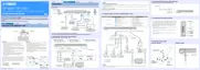
3. “p.SETINFORMATION” メニューを選択します。
(Fig.1)
● Preparation
1. Disconnect the power cable of this unit from the
AC outlet.
2. Remove the following parts. (For details, refer to
“DISASSEMBLY PROCEDURES”)
• Rear cover
• Bottom panel
• Cabinet L assembly
• Cabinet R assembly
• Top panel
• Top frame
• INPUT (1) P.C.B.
* Reconnect all cables (connectors) that have
been disconnected after disassembly.
● Operation procedure
1. Connect the power cable of this unit to the AC
outlet.
This unit is in standby mode.
2. Turn on power in self-diagnostic function mode.
(For details, refer to “SELF-DIAGNOSTIC
FUNCTION”)
3. Select “p. SET INFORMATION” menu. (Fig. 1)
p.SETINF p1.4300U
Sub-menu display
サブメニュー表示
Main menu display
メインメニュー表示
After a few seconds
数秒後
Fig. 1
54
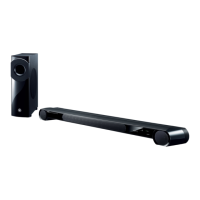
YSP-CU4300/YSP-CU3300/NS-WSW160
YSP-CU4300/YSP-CU3300/
NS-WSW160