AIR FILTER CASE
7-7
CAUTION:
ECA4C81020
• Make sure that the intake funnel smoothly
moves to the contacting surface between
upper stopper and lower seating position
when it is moved by hand.
• Make sure that the intake funnel smoothly
strokes from the upper position to the
seating position by its own weight.
EAS131004
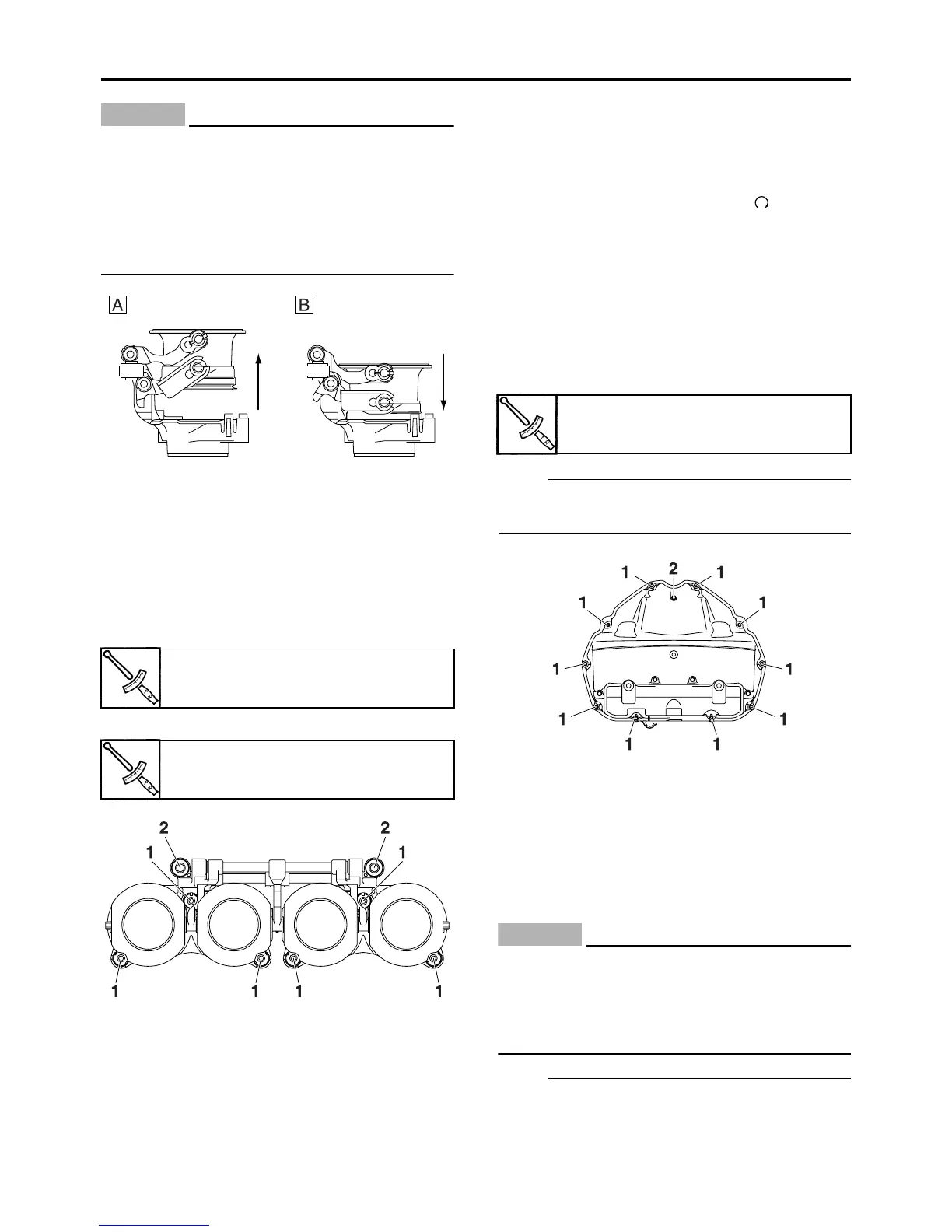
INSTALLING THE INTAKE FUNNEL
1. Install:
• Intake funnel servo motor rod assembly
• Intake funnel assembly
• Intake funnel joint bolts “1”
• Intake funnel joint bolts “2”
EAS4C81027
CHECKING THE INTAKE FUNNEL OPERA-
TION
1. Check:
• Intake funnel operation
▼▼▼▼▼▼▼▼▼▼▼▼▼▼▼▼▼▼▼▼▼▼▼▼▼▼▼▼▼▼
a. Activate the diagnostic mode and select
the diagnostic code number “34”.
Refer to “FUEL INJECTION SYSTEM” on
page 8-33.
b. Set the engine stop switch to “ ”.
c. Check that the intake funnel operate
smoothly strokes from the upper position to
the lower seating position.
▲▲▲▲▲▲▲▲▲▲▲▲▲▲▲▲▲▲▲▲▲▲▲▲▲▲▲▲▲▲
EAS13S1003
INSTALLING THE AIR FILTER CASE
1. Install:
• Upper air filter case
NOTE:
Tighten the upper air filter case bolts in proper
sequence as shown.
ET2C01006
INSTALLING THE FUEL HOSE (PRIMARY
INJECTOR FUEL RAIL SIDE AND SECOND-
ARY INJECTOR FUEL RAIL SIDE)
1. Connect:
• Fuel hose (primary injector fuel rail side
and secondary injector fuel rail side)
CAUTION:
EC2C01017
When installing the fuel hose, make sure
that it is securely connected, and that the
fuel hose connector cover on the fuel hose
is in the correct position, otherwise the fuel
hose will not be properly installed.
NOTE:
• Install the fuel hose securely onto the sec-
ondary injector fuel rail until a distinct “click”
is heard.
A. Upper
B. Lower
Intake funnel joint bolt
4 Nm (0.4 m·kg, 3.0 ft·lb)
Intake funnel joint bolt
3 Nm (0.3 m·kg, 2.2 ft·lb)
Upper air filter case bolt
2 Nm (0.2 m·kg, 1.5 ft·lb)

 Loading...