F
UEL
IN
JECTI
ON
AND
GOVERNOR
SYSTEMS
145
.:IfiJi'r
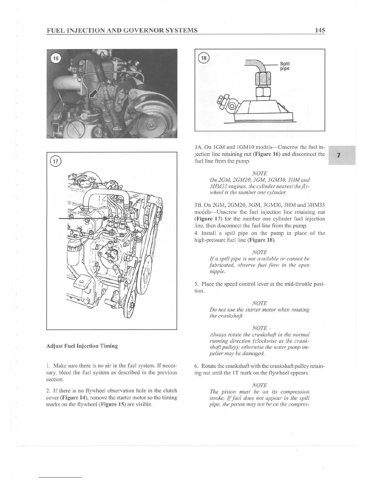
- Spill
pipe
7
NOTE
Do not use the
starter
motor
when rotating
the crankshaft.
NOTE
On 2GM, 2GM20, 3GM, 3GM30,
3HM
and
3HM35
engines, the cylinder nearest thefly-
wheel is the
number
one
cylinder.
5. Place the speed control lever at the mid-throttle posi-
tion.
NOTE
Jfa
spiff
pipe
is
not
available or cannot he
fabricated.
observe
fuet
flow
in the open
nipple.
38. On
20M,
2GM20, 3GM, 3GM30, 3HM and3HM35
models-Unscrew
the fuel injection line retaining nut
(Figu re 17) for the number
one
cylinder fuel injection
line, then disconnect the fuel line from the pump.
4. Install a spill pipe on the pump in place
of
the
high-pressure fuel line (Fig
ure
18).
3A. On IGM and IGMIO models
-Unscrew
the fuel in-
.----"
jcction line retaining nut (Figure 16) and disconnect the
fuel line from the pump.
Adjust Fucl lnjcction Timing
NOTE
Always
rotate the crankshaft in the
normal
running direction (clockwise at the crank-
shaft
pulley); otherwise the water
pump
im-
peller
may
be damaged.
1. Make sure there is no air in the fuel system.
If
neces-
sary, bleed the fuel system as described in the previous
section.
6. Rotate the crankshaft with the crankshaftpulley retain-
ing nut until the IT mark on the flywheel appears.
2. If there is no flywheel observation hole in the clutch
cover
(Figure
14), remove the starter motor so the timing
marks on the flywheel (Fi
gure
15) are visible.
NOTE
The piston
must
be 011 its
comp
ression
stroke.
If
fuel
does not
appear
in the spill
pipe
, the piston
may
1I0the on the compres-