22 YASKAWA ELECTRIC TOBP C730600 38C 1000-Series Option AI-A3 Installation Manual
6 Related Parameters
6 Related Parameters
The parameters outlined in the following sections are used to set up the drive for operation
with the option. Set parameters as needed. Parameter setting methods can be found in the
drive Quick Start Guide or Technical Manual.
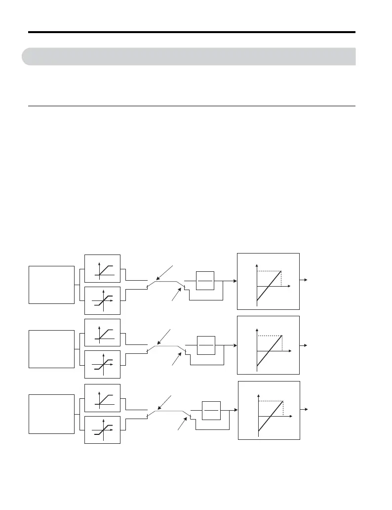
◆ Parameter F2-01
Set parameter F2-01 to select between separate input channels or combined inputs on the
option.
■ Setting 0: Separate Input Channels (default)
This setting replaces drive analog inputs A1, A2, and A3 with higher resolution signals in
terminals V1, V2, and V3 on the option.
H3- parameters set the function, gain, and bias for V1, V2, and V3. Refer to the drive
Technical Manual for details on setting these parameters.
Note: 1. When F2-01 = 0, the option cannot be selected as frequency reference source. Setting b1-01 to 3
(Option PCB as Frequency Reference Selection) when F2-01 is set to 0 will trigger an oPE05 error.
2. When F2-01 is set to 0, the drive automatically detects the selected signal level for each input.
Parameters H3-01, H3-05, and H3-09 do not need to be set, and the previous settings for these
parameters are disregarded.
Figure 12
Figure 12 Using the Option for Multi-Function Analog Inputs
AI-A3
V1 voltage input
(–10 to 10 V)
or
current input
(4 to 20 mA)
AI-A3
V2 voltage input
(–10 to 10 V)
or
current input
(4 to 20 mA)
AI-A3
V3 voltage input
(–10 to 10 V)
or
current input
(4 to 20mA)
Current input
(“I” position)
Voltage input
(“V” position)
Current input
(“I” position)
Voltage input
(“V” position)
Current input
(“I” position)
Voltage input
(“V” position)
T=H3-13
1
1+sT
Terminal V1 input switch
(S1)
Terminal V2 input switch
(S2)
Terminal V3 input switch
(S3)
H3-13
≠0
≠0
≠0
T=H3-13
1
1+sT
H3-13
H3-13
T=H3-13
1
1+sT
0
H3-08
H3-07
10 V
H3-12
H3-11
10 V
Input value (%)
Input voltageInput voltage
Input voltage
Input value (%)
Input value (%)
H3-04
H3-03
10 V
0
0
0%
100%
100%
-100%
0%
100%
100%
-100%
0%
100%
100%
-100%
Input value is
added to the
function selected
in H3-02
Input value is
added to the
function selected
in H3-10
Input value is
added to the
function selected
in H3-06

 Loading...


