7 Setting and Confirming CDBR Braking Unit Operation
YASKAWA ELECTRIC TOBP C720600 01E YASKAWA AC Drive Option CDBR-D, LKEB- Installation Manual 57
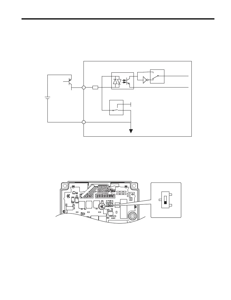
SOURCE Mode, External Power Supply
Set DIP switch S1 to SOURCE as shown in Figure 24 when controlling digital inputs by
PNP transistors (+24 V common/sourcing mode) and contact inputs using an external 24 V
power supply,
Figure 24
Figure 24 CDBR Braking Unit SOURCE Mode
■ Master/Slave Selection Switch (S2)
Leave DIP switch S2 set to the default setting OUT (Master) on the properly-configured
master CDBR. Set DIP switch S2 to IN (Slave) on all other units in the circuit. Refer to
Using CDBR Braking Units in Parallel on page 53 for details.
Figure 25
Figure 25 Master/Slave Selection Switch (S2)
+24 V
SINK-default
SOURCE
SB
SC
S1
S4
A (N.O. (default))
B
(N.C.)
24 V External
Power Supply
(24 Vdc)
IN (Slave)
OUT (Master)
TOBP_C720600_01E_9_0_E.book 57 ページ 2017年8月25日 金曜日 午後2時8分