3 Electrical Installation
YASKAWA ELECTRIC
TOEP C710606 15E - AC Drive V1000 - Quick Start Guide
EN 17
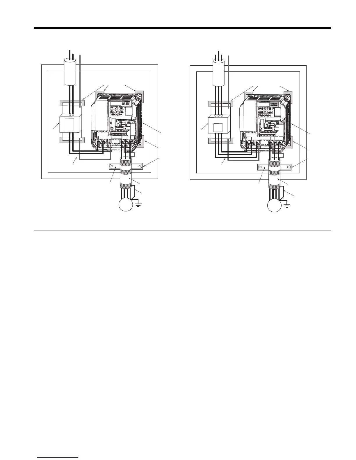
Figure 2 EMC Standards Compliant Wiring of Single and Three Phase Units
Main and Control Circuit Wiring
Wiring the Main Circuit Input
Consider the following precautions for the main circuit input.
• Use fuses recommended in Main Circuit on page 15 only.
• When using residual current monitoring or detection devices (RCM/RCD), make sure the
devices are designed for use with AC drives (e.g. type B according to IEC/EN 60755).
• If using a ground fault circuit breaker, make sure that it can detect both DC and high
frequency current.
• Use a DC reactor or AC reactor on the input side of the drive:
–To suppress harmonic current.
–To improve the power factor on the power supply side.
–When using an advancing capacitor switch.
–With a large capacity power supply transistor (over 600 kVA).
Wiring the Main Circuit Output
Consider the following precautions for the output circuit wiring.
• Do not connect any other load than a 3 phase motor to the drives output.
• Never connect a power source to the drives output.
 Loading...


