3 Wiring
E-19
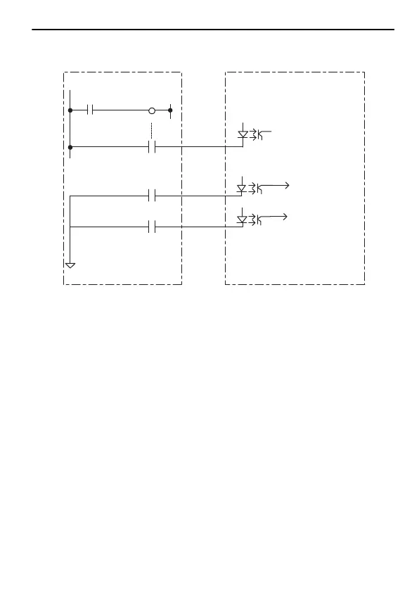
<Example Circuit Configuration>
* Design the circuits so that input and output signals from other input and
output devices are used only after the interlock signal turns ON.
Note: The MP3300 includes CPU Module and Base Unit.
The circuit configuration example is for an Output Module added to
the MP3300.
Interlock
output
CPU RUN
OB000000
SB000004
Interlock
signal input
Input and
output signals
∗
Other Input and Output Devices
SB000004: Always ON Coil
(ON while the CPU Module is operating normally.)
OB000000: Interlock output
MP3300 and Output Module
 Loading...


