19
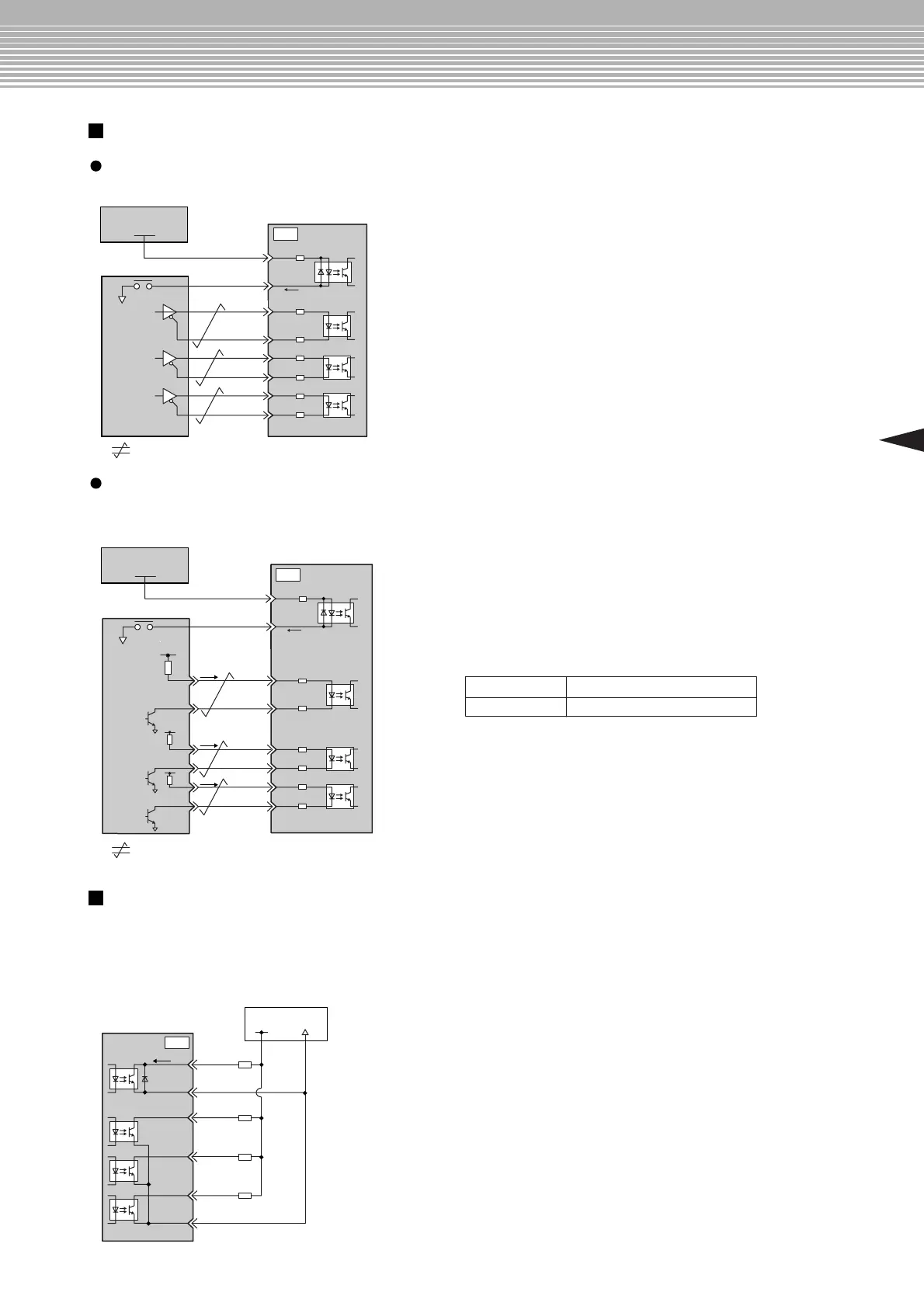
Applicable line driver: SN75174 or MC3487 (Manufactured by Texas Instruments or equivalent)
Set the R1 through R3 current limit resistors so that input current (i) will fall within the following range.
Input current (i) = 7 mA to 15 mA
*
:
Twisted-pair wires
Examples:
•
When Vcc is +24 V: R1 through R3 = 2.2 kΩ
•
When Vcc is +12 V: R1 through R3 = 1 kΩ
•
When Vcc is +5 V: R1 through R3 = 180 Ω
Note: The following signal logic applies for
an open-collector output.
Tr1 to Tr3 ON Equivalent to high level input
Equivalent to low level inputTr1 to Tr3 OFF
Connection Diagram
Connection Examples of Input Signal
Set the load so that the output current (i) will fall within 50 mA or less.
Photocoupler output (per output signal)
•
Max. voltage: 30 VDC
•
Max. current: 50 mADC
Connection Example of Output Signal
Line Driver Output
Open-collector Output
*
:
Twisted-pair wires
SERVOPACK
24-V Power supply
Photocoupler
Load
Load
Load
Load
10
50mA max.
+24V 0V
11
7
13
14
12
SG-PCO
ALM
/COIN
BK
SG-COM
PCO
CN1
SERVOPACK
Photocoupler
Host controller
1
2
9
8
4
3
/PULS
SIGN
/SIGN
CLR
/CLR
PULS
75Ω
7mA
*
CN1
75Ω
75Ω
75Ω
75Ω
75Ω
6
5
3.4kΩ
/S-ON
+24VIN
0V
24-V Power supply
+24V
Photocoupler
1
2
9
8
4
3
/PULS
SIGN
/SIGN
CLR
/CLR
PULS
*
Vcc
R1
i
R2
Tr1
Tr2
Tr3
R3
i
i
75Ω
75Ω
75Ω
75Ω
75Ω
75Ω
SERVOPACK
Photocoupler
Host controller
7mA
CN1
6
5
3.4kΩ
/S-ON
+24VIN
0V
24-V Power supply
+24V

 Loading...


