18
Pulse train references are given to control the position of the servomotor. The following pulse train output
forms are supported from the host controller.
•
Line driver output
•
+24-V open-collector output
•
+12-V open-collector output
•
+5-V open-collector output
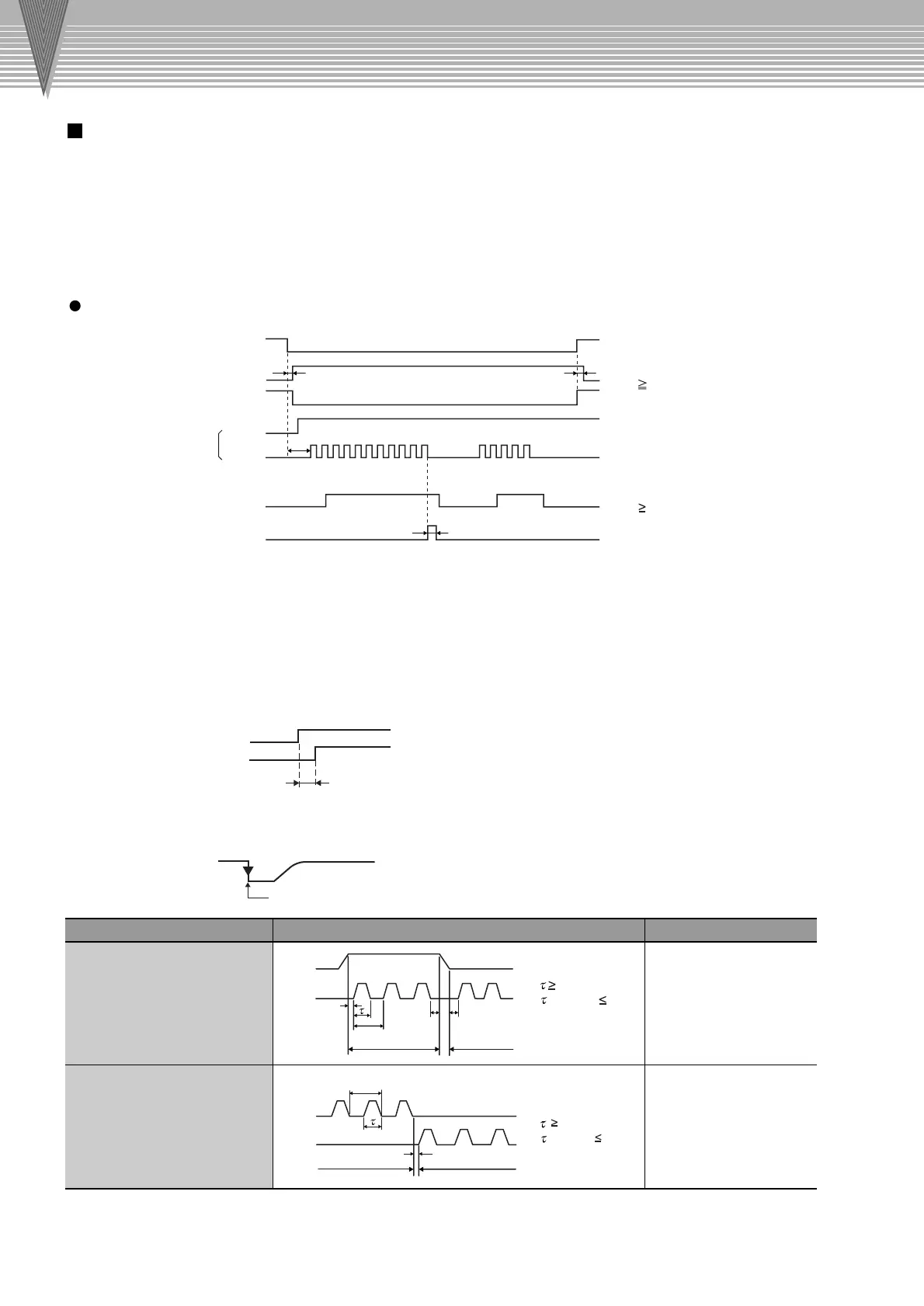
Servo ON (/S-ON)
Positioning completed (/COIN)
Clear (CLR)
Motor ON
Brake (/BK)
Sign + pulse train
Motor ON
Brake released
L
H
H
ON
ON
ON
t4
t3
t2
t1
*
1
:
The interval from when the servo ON signal is turned ON until the reference pulse is input
must be at least 40 ms, or the reference pulse may not be received by the SERVOPACK.
If a motor with a brake is in used, more time will be required to release the brake.
Therefore, provide an interval of at least 100 ms.
*
2
:
The error counter clear signal must be ON for at least 20 µs. If the reference pulse is stopped
when the clear signal is turned ON, the motor will stop at that position.
*
3
:
The lag time for the brake is 100 ms. Use a relay for brakes with an operating time of 30 ms
or less.
Notes: 1 The maximum lag time from the moment that an error or fault was detected until the
alarm signal turns ON is 2ms.
2 If using the phase-C output signal, use an edge when the signal changes from OFF
to ON at the beginning, so that the changes in the waveform from ON to OFF are
round edged.
Reference Pulse Signal Form Electrical Specifications Remarks
Sign + pulse train input
(SIGN + PULS signal)
Sign (SIGN):
High = Forward reference
Low = Reverse reference
Maximum reference frequency:
750 kpps (187.5 kpps for an
open-collector output)
CW pulse + CCW pulse
Maximum reference frequency:
750 kpps (187.5 kpps for an
open-collector output)
Forward reference
Reverse reference
t1
t2 t3
T
SIGN
PULS
Forward reference
Reverse reference
t1
T
CW
CCW
–
(SIGN)
(PULS)
Connection Diagram
Connection Diagram
Explanation of I/O Signals
I/O Signal Timing Examples
t1: Approx. 40 ms
t2: Approx. 130 ms
*
3
t3 40 ms
*
1
(Motor with brake: 100 ms)
t1, t2, t3 > 3µs
0.65µs
(
/T
)
×
100 50%
t1 >
3µs
0.65µs
(
/T
)
100 50%
t4 20 µs
*
2
2ms max.
Alarm detection
ALM
PCO
Edge when the signal changes from OFF to ON

 Loading...


