6.2 Function List
6-4
6.2 Function List
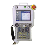
Programming
Pendant
Operation
Coordinate System Joint, Rectangular/Cylindrical, Tool, User Coordinates
Modification of
Teaching Points
Adding, Deleting, Correcting (Robot axes and external axes
respectively can be corrected.)
Inching Operation Possible
Path Confirmation Forward/Reverse step, Continuous feeding
Speed Adjustment Fine adjustment possible during operating or pausing
Timer Setting Possible every 0.01 s
Short-cut Function Direct-open function, Screen reservation function
Interface CF (Compact Flash) card slot (At Programming Pendant)
RS232C (At Control Circuit Board)
LAN (100 BASE-TX/10BASE-T) (At Control Circuit Board)
(Option)
Application Arc welding, Spot welding, Handling, General, Others
Safety
Feature
Essential Measures Designed in accordance with UL, ANSI/RIA standard
Running Speed
Limit
User definable
Enable Switch 3 position type. Servo power can be turned on at the middle
position only. (Located on programming pendant)
Collision-proof
Frames
S-axis frame (doughnut-sector), Cubic frame (user coordi-
nate)
Self-Diagnosis Classifies error and two types of alarms (major and minor)
and displays the data
User Alarm Display Possible to display alarm messages for peripheral device
Machine Lock Test-run of peripheral devices without robot motion
Door Interlock A door can be opened only when a Disconnect switch is off.
Maintenance
Function
Operation Time
Display
Control power-on time, Servo power-on time, Playback time,
Operation time, Work time
Alarm Display Alarm message and previous alarm records
I/O Diagnosis Simulated enabled/disabled output possible
T.C.P. Calibration Automatically calibrates parameters for end effectors using a
master positioner

 Loading...


