6.4 Equipment Configuration
6-6
6.4 Equipment Configuration
The NX100 is comprised of individual units and modules (circuit boards). Malfunctioning com-
ponents can generally be easily repaired after a failure by replacing a unit or a module.
This section explains the configuration of the NX100 equipment.
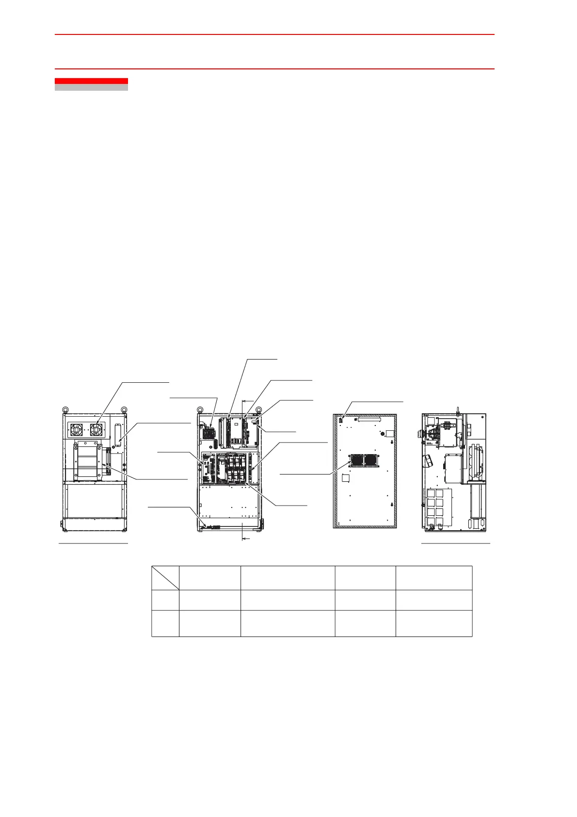
6.4.1 Arrangement of Units and Circuit Boards
" Configuration
The arrangements of units and circuit boards in small-capacity, medium-capacity, and large-
capacity NX100s are shown.
Small Capacity
SERVOPACK Fuse Disconnect Switch Power Supply Contact Unit
Configuration 1 for Small-Capacity NX100
NJ2096-
DATE
SER!!NO.
JAPAN
TYPE
YASKAWA!!!ELECTRIC!!!CORPORATION
OFF
REV.
(Arc!Welding!Apprication)
HP3
JZRCR-NTU01-2
ATDR5!5A!*
ERCR-EA1400N-AB00
HP6
EA1400N
SGDR-EA1400N
Step-down!Transformer
(Disconnect!Switch)
CPU!Unit
JZNC-NRK01
CPS-420F
Supply
Control!Power
Robot!I/F!Unit
JZNC-NIF01
Circuit!Board
SGDR-AXA01A
Major!Axes!Control
ATDR5!3A!*
JZRCR-NTU01-2
Contactor!Unit
Power!Supply
Fuse
(Converter!Intergrated)
SERVOPACK
SGDR-EA1400NY26
Model
NX100
Type
ERCR-HP3-AB00
(with!removed!cover)
Back!View
(220W,12.5!
Ω
)
MRC22-125K-220W-12.5
Regenerative!Resistor
(For!air!inlet)
4715MS-22T-B50-B00
(MXT)
Terminal!Block
Robot!System!input
following!table
Refer!to!the
Power!Supply
Contactor!Unit
Fuse!Disconect!Switch
194RF-NC030R14
JANCD-XEW01
Welding!Circuit!Board
following!table
Refer!to!the
SERVOPACK
(Air!flows!down)
4715MS-22T-B50-B00
Backside!Duct!Fan
Emergency!Stop!Button
Sectional!View!A-A'
A
A'
Interior!Circulation!Fan
HW1B-V404R
*!3-phase!480!AVC,!with!built-in!transformer
LAN0 COM
Front!Side
CN3
CN1
BOTTOM!CONNECTER!VIEW
CPS-420
CN6
LAN1
CPUPCI PCI
EXT
CN1
AXIS
CN2
CN2CN1
PCINIF
Back!Side
CN3
Option!PCI!Slot!#CPU2
Option!PCI!Slot!#CPU1
Option!PCI!Slot!#AXIS
17
07
27
JAPAN
201918
100908
302928
SUPPLY
12
02
22
Electric
CPS-NX1
POWER
No.
11
01
21
Fuji
DATE
16151413
06050403
26252423
Co.,Ltd.
S
G
TUV
HJK
LM
AB
NPQR
CDEF
FF
EE
UU
FF
EE
SS
UU
SS
XEW01-
JANCD-
CN04F2F1
CN03
S1
CN02CN01
SOURCE
OHT
PON
FAN
OTHER
+24V
+5V
+5VSB
(+24V1)
CN05
CN01
(AC!IN)
CN03
(+24V2)
CN04
(TU)
INPUT
CN02
(REMOTE)
50/60Hz
3A
200-240V!AC
WARNING
based!!on!!local!!code.
Ground!!the!!earth!!terminal
electric!!shock.
May!!cause
WARNING
based!!on!!local!!code.
Ground!!the!!earth!!terminal
electric!!shock.
May!!cause
WARNING
High!Voltage
Do!not!open!the!cover.
CN08
5A!125V
3FU
CN06
CN07CN05
CN04
2FU
10A!250V
1FU
10A!250V
4X
CN03CN02
CN01 SW1
3X
2X
1X
E
F
C
4
2
D
3
6
B
A
9
8
7
5
PEPE

 Loading...


