10
5 Wiring
5.1 Terminal Functions
* Up to +14 V ±5 % can be supplied by adjusting variable resistor RV1.
RV1 is set to 13.0 V at the factory prior to shipment.
PG Signal Output
The PG signal output (phases A and B) may vary according to installation location on the
motor. Refer to Fig. 4 for correct wiring.
In general, motor forward direction is counterclockwise (CCW) as viewed from the load
shaft. For YASKAWA’s motor, phase A of PG output leads phase B by a phase angle of 90°
in clockwise (CW) rotation. According to PG, phase A lags phase B by a phase angle of 90°
in clockwise (CW) rotation. In this case, when PG is installed at the opposite drive end, con-
nect phases A and B output from PG to the option card as it is.
For YASKAWA’s Inverter motor with PG, PG is installed at the opposite drive end. Then,
phase A lags phase B by a phase angle of 90° at motor forward run. (Motor runs CCW as
viewed from PG.) Therefore, when using this motor or similar motors, connect phases A
and B to the option card after replacing phase output. The pulse monitor on this option
shows phase A leading phase B by a phase angle of 90°.
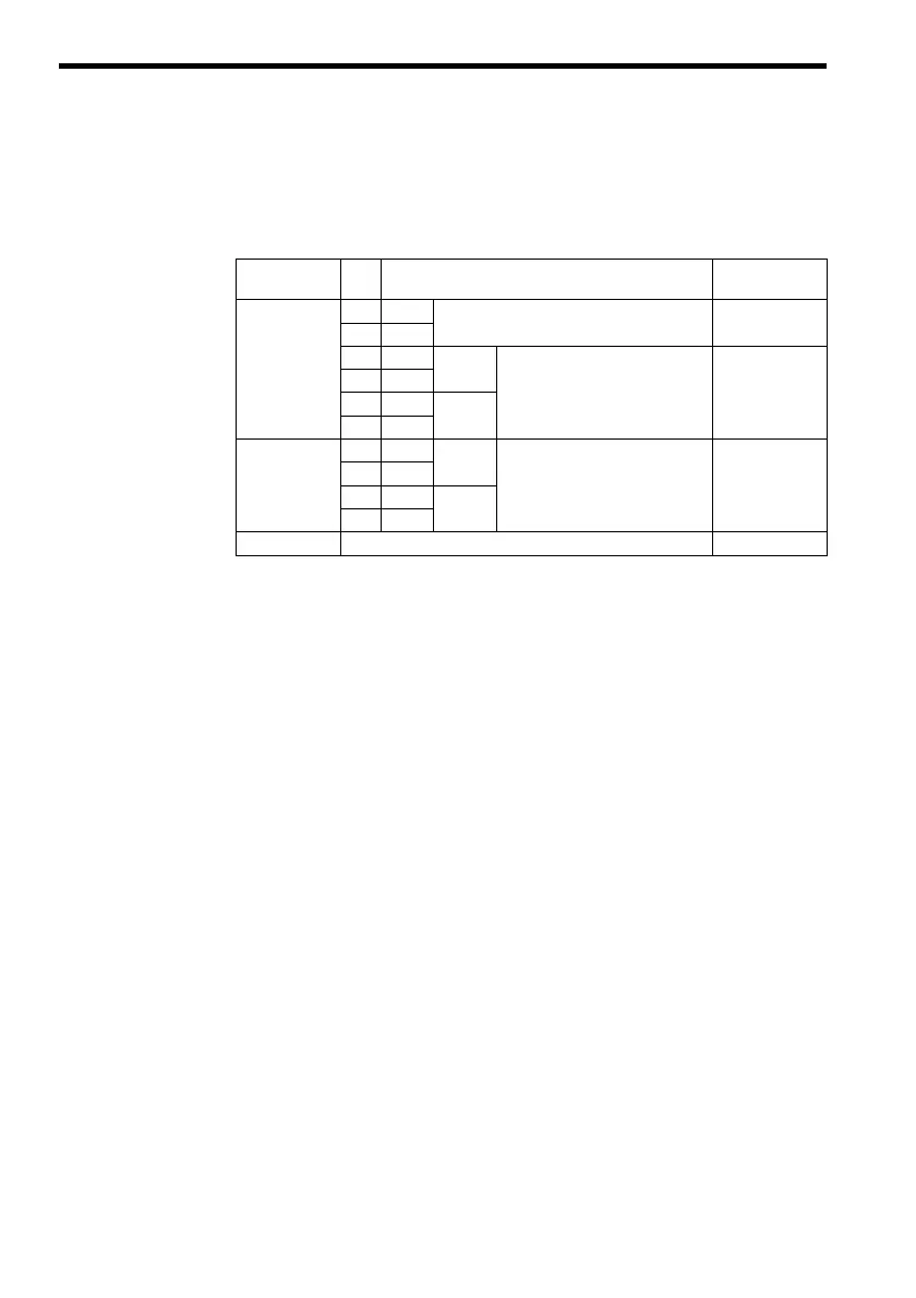
Table 1 Terminal Functions of PG-B2
Terminal Block
Symbol
Pin
No.
Functions Remarks
TA1 1 +12 V +12 V power supply
(+12 V ±5 %, maximum current 200 mA)
*
Power supplies
for PG
20 V
3+A Pulse
Encoder (Pulse generator, PG)
signal input.
Signal input level
H: +8 V to +12 V
L: +1 V or lower
4 −
5+B Pulse
6 −
TA2 1 + A Pulse
Pulse monitor output. Open collector
24 V max.
30 mA max.
2 −
3+B Pulse
4 −
TA3 Shielded sheath connection terminal