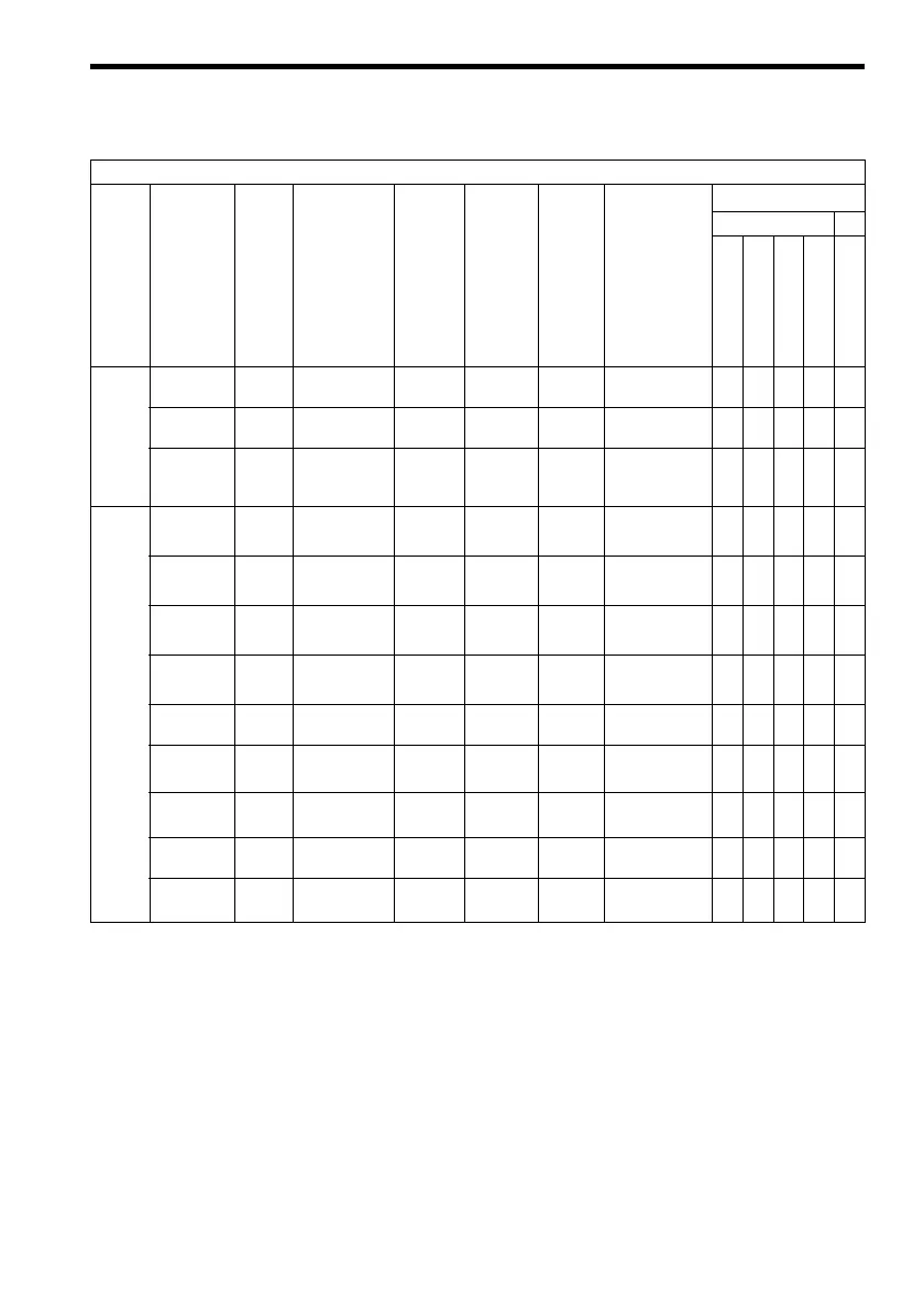
7 PG-B2 Card Parameter List
15
* 1. { = Enable, × = Disable
* 2.
{ = Setting enable, × = Setting disable
* 3. For flux-vector control
* 4. For V/f with PG feedback control
* 5. For the F7, setting and reference are enabled for the software No. (U1-14) of 1030 or after.
* 6. ASR - Automatic Speed Regulator
* 7. For the G7 only
* 8. If using the flux-vector control with the F7, be sure to use an Inverter with a design revision
number of E or later. Versions C or earlier do not support the flux-vector control.
PG
Option
Setup
PG# Gear
Teeth 1
F1-12 Number of PG
gear teeth 1
0 to 1000 0
××{ ×××
PG# Gear
Teeth 2
F1-13 Number of PG
gear teeth 2
0 to 1000 0
××{ ×××
PGO Detect
Time
*5
F1-14 PG open-cir-
cuit detection
time
0 to 10 s 2 s
××{ × { ×
ASR
Tuning
*6
ASR P Gain
1
C5-01 ASR propor-
tional (P) gain 1
0 to
300.00
20.00
*3
(0.20)
*4
{ × { × {{
ASR I Time
1
C5-02 ASR integral (I)
time 1
0 to
10.000 s
0.500 s
*3
(0.200 s)
*4
{ × { × {{
ASR P Gain
2
C5-03 ASR propor-
tional (P) gain 2
0 to
300.00
20.00
*3
(0.02)
*4
{ × { × {{
ASR I Time
2
C5-04 ASR integral (I)
time 2
0 to
10.000 s
0.500 s
*3
(0.050 s)
*4
{ × { × {{
ASR Limit C5-05 ASR limit 0.0 to 20
%
5.0 %
*4
××{ ×××
ASR Delay
Time 1
*8
C5-06 ASR primary
delay time 1
0.000 to
0.500 s
0.004 s
*3
× ×××{{
*3
ASR Gain
SW Freq
*8
C5-07 ASR switching
frequency
00 to
400.00 Hz
0.0 Hz
× ×××{{
ASR Limit
*8
C5-08 ASR integral (I)
limit
0 to 400 % 400 %
× ×××{{
ASR Delay
Time 2
*7
C5-10 ASR primary
delay time 2
0.000 to
0.500 s
0.010 s
× ××××{
Table 3 PG-B2 Card Parameter List (cont’d)
PG-B2 Card Parameter List
Digital
Operator
Function
Group
Digital
Operator
Display
Param-
eter
No.
Parameter
Name
Setting
Range
Factory
Setting
Change
During
Opera-
tion
*1
Data Selection
Control Method
*2
G5, G7, F7 G7
V/f Control
V/f w/PG Fdbk
Open loop Vector
Flux Vector
*9
Open loop Vector 2