5 Installation Procedure
YASKAWA ELECTRIC TOBP C730600 37B 1000-Series Option PG-X3 Installation Manual 17
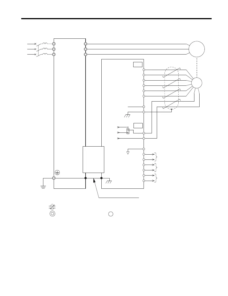
Figure 7
Figure 7 PG-X3 Option and PG Connection Diagram
<1> Ground the shield on the PG side and the drive side. If noise problems arise in the
PG signal, remove the shield ground from one end of the signal line or remove the
shield ground connection on both ends.
U/T1
V/T1
W/T1
R/L1
S/L2
T/L3
A+
A
B
Z
B+
Z+
a+
a
b
z
b+
z+
FE
IP
IG
IP12
IP5
IG
TB1
SG
SD
TB2
PG
NC
CN5-B
or
CN5-C
A channel monitor signal
Ground wire
B channel monitor signal
Z pulse monitor signal
YASKAWA
Drive
PGX3
Option
CN3
M
FE
twisted-pair shielded line
main circuit terminal control circuit terminal
<1>