20.2.46 S4-DIGIT COMMAND EXTERNAL OUTPUTS
(SB1 THROUGH SB16) AND S5-DIGIT COMMAND
EXTERNAL OUTPUTS (SDA1 THROUGH SDA16 OR
SDI1 THROUGH SD116)
These inputs and outputs are used, when the control is of S5-digit
analog output or non-contact output to output the results of the
operation by the S command in the part program to the outside and
perform the actual S5-digit command 12-bit non-contact output or
analog output according to the inputs from the outside.
(1) S5-Digit Command 12-Bit Non-Contact Output
Output of operation results to outside: SBL through SB 12
(2) S5-Digit Command Analog Output
(a) Output of operation results to outside: SDA1 through SDA16.
Note: The input/output value is signed binary 16-bit.
The relationship with analog voltage is as follows.
-32768 to O to +32767
1
I
-1OVto Ov to +Iov
I
(b) Input from outside for outputting analog voltage to DAS.
SGSO: SDI1 through SDI16.
The primary purpose of this function is to control the S5-digit
analog output command or non-contact output command by the
sequencer built in the control. This function should not be used for
other purposes unless specifically required. Operation results are
output selectively to the outside directly by NC or via outside
inputs, depending on the setting of parameter #6032, D2. Set
#6032, D2 to” 1” tp output via outside inputs.
20.2.47 EXTERNAL INPUT, VERIFY AND OUTPUT
SIGNALS (EIN, EVER, EOUT, ECLM, IER, EDTS)
These signals are to command input, verification, and output of part
programs to the part program memory by means of external signals.
•1
# 13182
I 04
EOUT _
EXTERNAL OUTPUT
&
# 12236 ‘
EDTS
EDIT CONDITION
COM
Fig. 20.28
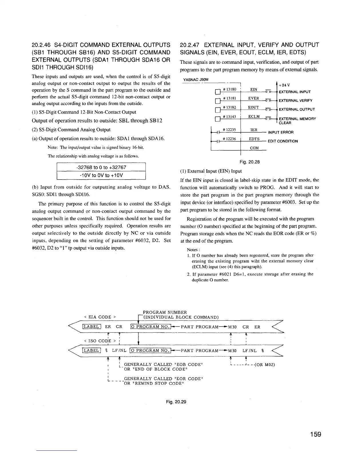
(1) External Input (EIN) Input
If the EIN input is closed in label-skip state in the EDIT mode, the
function will automatically switch to PROG. And it will start to
store the part program in the part program memory through the
input device (or interface) specified by parameter #6003. Set up the
part program to be stored in the following format.
Registration of the program will be executed with the program
number (O number) specified at the beginning of the part program.
Program storage ends when the NC reads the EOR code (ER or %)
at the end of the program.
Notes :
1. If O number has already been registered, store the program after
erasing the existing program wiht the external memory clear
(ECLM) input (see (4) this paragraph).
2. If parameter #6021 D6= 1, execute storage after erasing the
dupIicateO number.
PROGRAM NUMBER
< EIA CODE >
r(INDIVIDUAL BLOCK COMMAND)
,
1
-
ER CR [0 PROGRAMNO*
PART PROGRAM— M30 CR ER
T T
I
—
4
+
< ISO COD’E > ~
I
= ~ LF/NL (0 pROGRA~
-F==?
PART PROGRAM— M30
:.
I
GENERALLY CALLED “EOB CODE”
, OR “END OF BLOCK CODE”
: . . . .. J--. (ORM13,2)
I
~ . _ _ -GENERALLY CALLED ‘lEOR CODE1l
OR “REWIND STOP
CODE”
Fig. 20.29
 Loading...


