APPENDIX 2 LIST OF PARAMETER NUMBERS
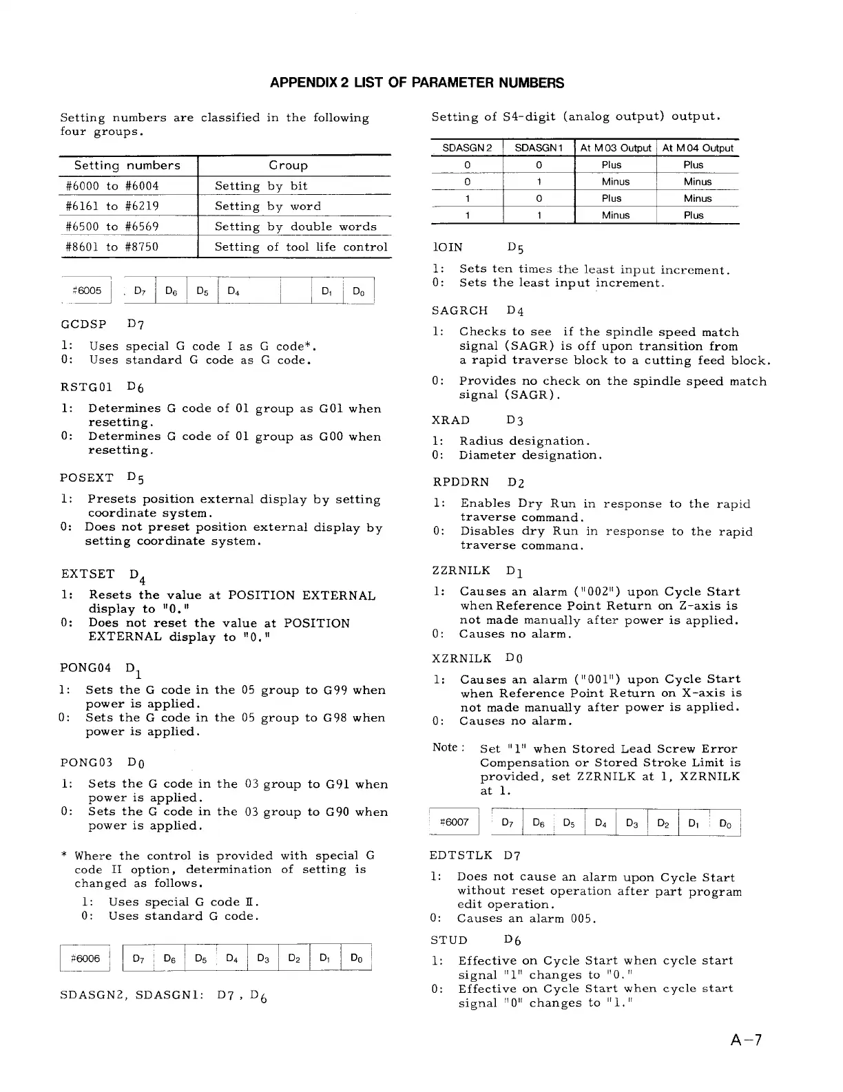
Setting numbers are classified in the following
four groups.
Setting numbers
Group
#6000 to #6004
Setting by bit
#6161 to #6219
Setting by word
#6500 to #6569
Setting by double words
#8601 to #8750
Setting of tool life control
:7 .mD~:-~
<mo5
—J
GCDSP
D7
1:
Uses special G code I as G code*.
o:
Uses standard G code as G code.
RSTGO1 D6
1: Determines G code of 01 group as GO1 when
resetting.
o:
Determines G code of 01 group as GOO when
resetting.
POSEXT D5
1: Presets position external display by setting
coordinate system.
O: Does not preset position external display by
setting coordinate system.
EXTSET D4
1:
Resets the value at POSITION EXTERNAL
display to “O. ‘1
o: Does not reset the value at POSITION
EXTERNAL display to “O. “
PONG04 Dl
1: Sets the G code in the 05 group to G99 when
power is applied.
o:
Sets the G code in the 05 group to G98 when
power is applied.
PONG03 DI)
1: Sets the G code in the 03 group to G91 when
power is applied.
o: Sets the G code in the 03 Erouw to G90 when
power is applied.
* Where the control is provided
code II option,
determination
changed as follows.
1: Uses special G code E.
o:
Uses standard G code.
——
$W06 ;
Lq-
SD ASGN2, SD ASGN1: D7 ,
D6
with special G
of setting is
m
Setting of S4-digit (analog output) output.
—%.1>
I
Plus
I
Plus
o
1
I
Minus Minus
1
0 Plus
Minus
1
Ill
Minus I
Plus
10IN
D5
1:
Sets ten times the least input increment.
o:
Sets the least input increment.
SAGRCH
D4
1:
Checks to see if the spindle speed match
signal ( SAGR) is off upon transition from
a rapid traverse block to a cutting feed block.
o:
Provides no check on
signal (,sAGR).
XRAD
D3
1:
Radius designation.
o: Diameter designation.
RPDDRN D2
the spindle speed match
1:
Enables Dry Run in response to the rapid
traverse command.
o:
Disables dry Run in response to the rapid
traverse commana.
ZZRNILK D 1
1:
Causes an alarm (” 002”) upon Cycle Start
when Reference Point Return on Z–axis is
not made manually after power is applied.
o: Causes no alarm.
XZRNILK DO
1:
Causes an alarm (” 001”) upon Cycle Start
when Reference Point Return on X-axis is
not made manually after power is applied.
o: Causes no alarm.
Note : Set II111when Stored Lead Screw Error
Compensation or Stored Stroke Limit is
provided, set ZZRNILK at 1, XZRNILK
at 1.
ED TSTLK D7
1: Does not cause an alarm upon Cycle Start
without reset operation after part program
edit operation.
O: Causes an alarm 005.
STUD
D6
1:
Effective on Cycle Start when cycle start
signal “l” changes to “O. “
o: Effective on Cycle Start when cycle start
signal
11011
changes to “1.“
A–7

 Loading...


