2.6.5.3 Operation Expression for Coordinate System
Setting
The following
is the operation expression for
coordinate system setting at various time
frequencies ?
X-axis coordinate value = Machine position + tool
coordinate memory +
work coordinate system
shift amount
Z-axis coordinate value = Machine position + tool
coordinate memory +
work coordinate system
shift amount
( 1) The machine position is called the position
machine.
( 2 )
The tool coordinate memory value number is
of two types; the number when the timing for
the next coordinate system setting is manual
and when it is automatic.
(3) The work coordinate system shift amount is
called the offset TOO, X, or Z data.
2.6.5,4 Timing of Coordinate System Setting under
the Manual Mode
Under the manual mode, coordinate system setting
is made with the following times (a) to (c) .
The
tool coordinate memory number is created from the
tool number binary value set in 1/0 input #13174
(TP1) to #13178 (TP8) , to be used for operation.
The coordinate system can also be set up
inside the NC,
or by a request from the
sequencer.
When set by a request of the
sequencer, coordinate system setting is executed
to turn on output #12194 (end of coordinate system
setting output) when
input #13127 (coordinate
system setting request input) turns on.
(a) Upon zero point return. (NC internal setting
at label skip, or sequencer setting for other
cases. )
(b) On the tool
setter, when the tool nose
contacts the sensor upon measurement.
(NC
internal setting)
(c) When turret indexing is performed by manual
operation,
(Sequencer setting )
Note :
Coordinate system cannot be set by manual
operation, when parameter #6011 DO = 1 [when the
tool coordinate memory number follows the last two
digits of T**$$I.
2.6.5,5 Timing of Coordinate System Setting under
the Automatic Mode
Under the automatic mode, coordinate system
setting is performed when the turret is called up
by the T code.
The tool coordinate memory
number uses the turret number commanded on the
command screen or the offset number for
operation.
Unlike the conventional offset method, the T
code command in the coordinate system setting
specification is given as follows.
The setting of parameter #6011 DO decides
whether to set the tool coordinate memory number
at the front two digits of T4-digit, or at the last
two digits of the T4-digit,
The execution of the coordinate system
setting differs as follows, by the parameter
setting.
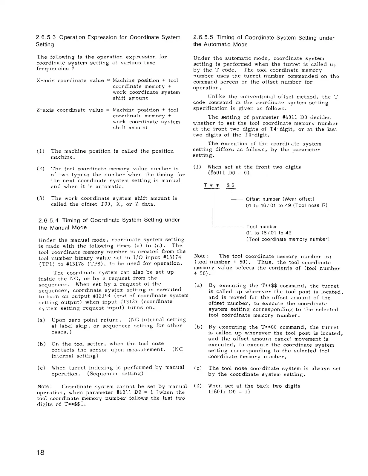
(1) When set at the front two digits
(#6011 DO = O)
T** $$
T—
~
— Offset number (Wear offset)
01 to 16/01 to 49 (Tool nose R)
,_
—— Tool number
01 to 16/01 to 49
(Tool coordinate memory number)
Note :
The tool coordinate memory number is:
(tool number + 50).
Thus, the tool coordinate
memory value selects the contents of (tool number
+ 50).
(a)
(b)
(c)
(2)
By executing the T**$$ command, the turret
is called up wherever the tool post is located,
and is moved for the offset amount of the
offset number, to execute the coordinate
system setting corresponding to the selected
tool coordinate memory number.
By executing the T**OO command, the turret
is.called up wherever the tool post is located,
and the offset amount cancel movement is
executed, to execute the coordinate system
setting corresponding to the selected tool
coordinate memory number,
The tool nose coordinate system is always set
by the coordinate system setting.
When set at the back two digits
(#6011 DO = 1)
18

 Loading...


