In this step the motor is checked for proper direction
and operation. This test is to be performed solely
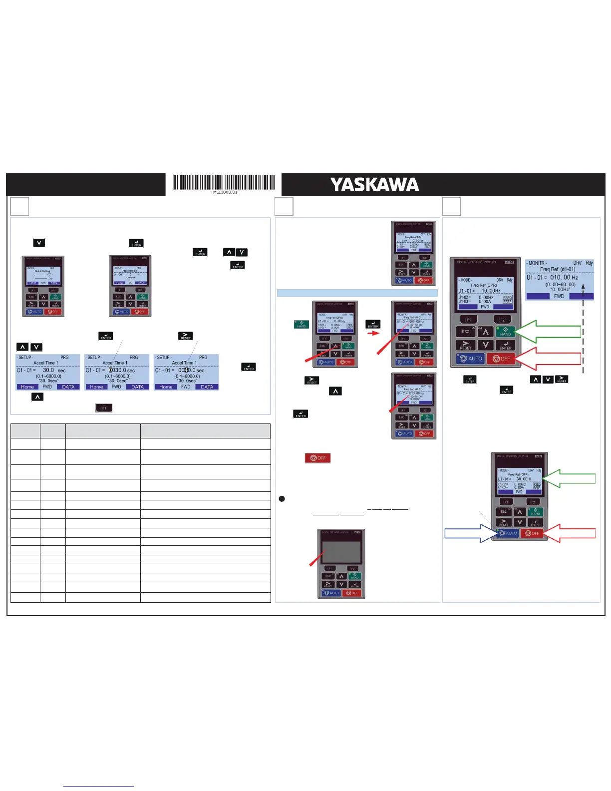
from the digital operator. Apply power to the Z1000
after all the electrical connections have been made
and protective covers have been re-attached. At
this point, D
, the Digital
Operator should display as shown in
Use precaution, and refer to
output leads to the motor
(U/T1, V/T2 and W/T3). After the
wiring change, repeat
and recheck motor direction.
After the power has been turned OFF, wait at
least five minutes until the
charge indicator extinguishes
completely before touching any wiring, circuit
boards or components.
DANGER
If motor rotation is not correct, power down the drive, wait five minutes and
swap two motor leads at
the drive output terminals.
!
Next, press to move the cursor one
position to the right and to increase the
frequency reference (d1-01) to 10.00 Hz.
Press to save freq. reference.
The motor should now be operating at low speed
running in the correct forward (clockwise) direction.
Next, press on the Digital Operator.
Digital Operator
turned off.
First Digit
Flashing
Press
Green LED
is blinking.
10.00 Hz
Check Motor Rotation and Direction
Hand / Auto Mode Operation
Page 2 of 2
This step shows how to set up the most important parameters using the Z1000 Quick Setup function. Apply power to the Z1000
after all the electrical connections have been made and the terminal cover has been re-attached. At this point D
he digital operator should be reading as shown in
. to the right.
After selecting the Application the Z1000 Quick Setup will display the dedicated application parameters to set up your Z1000
Drive for the selected application. Press to access a parameter, and use to select the digit and use
to change the parameter value.
Press
to save the value.
Press to go to the next parameter to continue the Quick Setup programming.
When Quick Setup is completed press “Home” to exit the Quick Setup menu and go to operation.
Frequently Used Parameters
Press three times until the
digital operator shows the Quick Setting menu.
1.
Press to start the
Quick Setup.
2.
Select Application
3.
Press and use to switch
between applications. Press to select.
Available Applications:
0:
General: Basic Drive Operation
Fan General: Fan Application without PI Control
Fan Application with PI Control
Return Fan with PI Control
Cooing Tower Fan without PI Control
Cooling Tower Fan with PI Control
Pump (Secondary) without PI Control
Pump with PI Control
Parameter
Default
Value
Description Comments
A1-06 0 Application Selection See Application list under step 4.
b1-01 1
Reference Source 1
Speed Control Method
0 = Digital Operator (Adjust Motor Speed from keypad)
1 = Terminals (Speed Pot. / 0 – 10V / 4—20mA)
b1-02 1
Run Source 1 /
Start/Stop Control Method
1 = Terminals (Start/Stop using external contact / switch)
3 = Communication
b1-03 1 Stop Method Selection
0 = Ramp to stop (Motor ramps down at stop command)
1 = Coast to stop (Motor freewheels at stop command)
b5-01 0 PI Mode Selection 0 = Disabled, 1 = Enabled, 3 = Fref + PI
b5-02 2.00 PI Proportional Gain Setting Only active when b5-01 is set to value greater than 0
b5-03 0.5 sec. PI Integral Time Setting Only active when b5-01 is set to value greater than 0
b5-20 1 PI Setpoint Scaling 0 = Hz,1= %, 2 = rpm, 3 = custom (use b5-38, b5-39 and b5-41)
C1-01 30.0 sec. Acceleration Time The time it takes to ramp up from 0 to maximum motor speed.
C1-02 30.0 sec. Deceleration Time The time it takes to ramp down from maximum motor speed to 0.
d2-01 100.0 % Frequency Reference Upper Limit Maximum motor speed allowed (e.g. 100 % = Max rpm)
d2-02 0.0 % Frequency Reference Lower Limit Minimum motor speed allowed (e.g. 100 % = Max rpm)
E1-01 * Input Voltage Setting Motor nameplate voltage
E2-01 * Motor Rated Current Motor nameplate current
H3-09 1 Terminal A2 Signal Level Selection 0 = 0 to 10V, 1 = -10 to 10V, 2 = 4 to 20mA, 3 = 0 to 20mA
H3-10 1 Terminal A2 Function Selection Predefined signals, see Z1000 User Manual
The Z1000 can be operated in HAND mode when the following actions have been
performed:
· All parameters are programmed
· Motor direction has been checked
button to put the Z1000 into AUTO mode.
In AUTO mode the Z1000 is capable of starting or stopping based on the Run
Source Selection setting parameter b1-02. (See Step 3 Select Start/Stop
Control Method)
The Speed Command used in AUTO mode is based on the Reference Source
Selection setting parameter b1-01. (See Step 3 Select Speed Method)
The Z1000 can be operated in AUTO mode when the following actions have been
performed:
· All parameters are programmed
· Motor direction has been checked
· Auto Mode: Reference source selected in parameter b1-01 (See step 3)
· Auto Mode: Run source selected in parameter b1-02 (See Step 3)
Press to access Hand Speed. Use to change
Hand Speed value. Press to save value.
PRESS HAND BUTTON
PRESS TO TURN OFF
PRESS AUTO BUTTON PRESS TO TURN OFF
AUTO REFERENCE
LED is blinking
when AUTO mode
is active but AUTO
Run Command is
not active.
YAI Document Number: TM.Z1000.01 01/20/2016 ©2012-2016 Yaskawa America, Inc. - (800) YASKAWA (927-5292) Fax (847) 887-7310 DrivesHelpDesk@yaskawa.com www.yaskawa.com
Z1000 AC Drive
Quick Start Procedure

 Loading...


