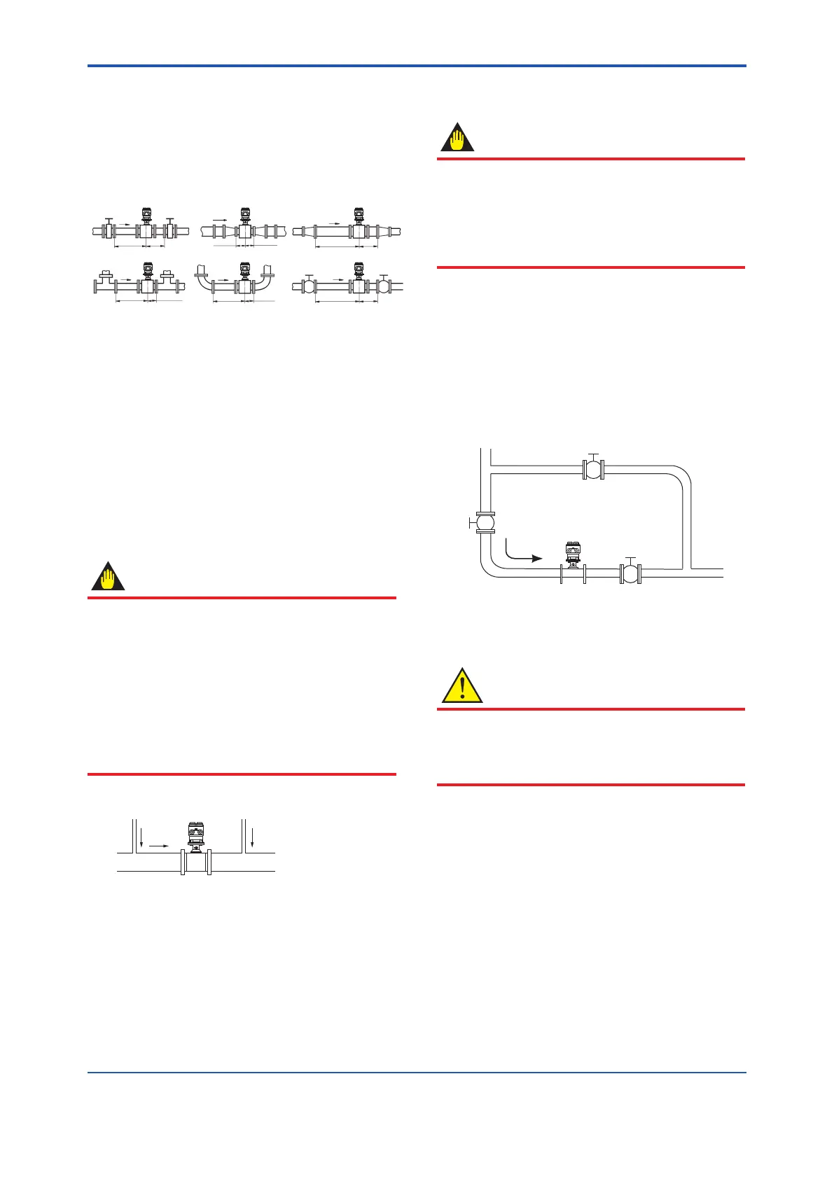
(3) Required Lengths of Straight Runs
Based on JIS B 7554 “Electromagnetic Flowmeters” and
our piping condition test data, we recommend the piping
conditions as shown in the following gures. This is not
always enough when the piping line incorporates multiple
conditions at the same time.
Gate valve
fully open
5D or more
2D
or more
Reducer
pipe
Expander
pipe
0 is allowable. 0 is allowable.
10D or more
10D or more
Tee
90-degree bend
Various valves
0 is allowable.5D or more 0 is allowable.5D or more
2D
or more
Figure 3.1.1 Required Lengths of Straight Runs
*1: Do not install anything in the vicinity that may interfere
with the magnetic eld, induced signal voltages, or ow
velocity distributions of the owmeter.
*2: A straight run may not be required on the downstream
side of the owmeter. However, if a downstream valve
or other tting causes irregularity or deviation in ows,
provide a straight run of 2D to 3D on the downstream side.
*3: The valves shall be mounted on the downstream side so
that deviated ows do not occur in the sensor and to avoid
startup from an empty condition.
*4: In case the piping conditions are compounded, install
on the straight pipe section where the upstream part is
sufciently rectied.
(4) Maintaining Stable Fluid Conductivity
IMPORTANT
Do not install the owmeter where uid conductivity
tends to become uneven. If chemicals are fed near
the upstream side of a magnetic owmeter, they may
affect the ow rate’s indications. To avoid this situation,
it is recommended that the chemical feed ports be
located on the downstream side of the owmeter. If
it is unavoidable that chemicals must be fed on the
upstream side, provide a sufcient length of straight
run (approximately 50D or more) to ensure the proper
mixture of uids.
Upstream side
Figure 3.1.2 Chemical Injection
(5) Precautions for Use of Liquid Sealing
Compounds
IMPORTANT
Care must be taken in using liquid sealing compounds
on the piping, as it may have a negative inuence on
the ow indications by owing out and covering the
surfaces of an electrode or grounding ring. In particular,
care must be taken if a liquid sealing compound is used
in the case of vertical piping.
(6) Service Area
Select locations where there is adequate space to service
installing, wiring, overhauling, etc.
(7) Bypass Line
It is recommended to install a bypass line to facilitate
maintenance and zero adjustment.
Block valve
Figure 3.1.3 Bypass Line
(8) Supporting the Flowmeter
CAUTION
Do not secure the owmeter separately to prevent the
vibrations, shocks, and expansion and contraction forces
of the piping from affecting it. Fix the pipes rst, then
support the owmeter with the pipes.
<3. Installation>
10
IM 01E24A01-01EN
 Loading...

